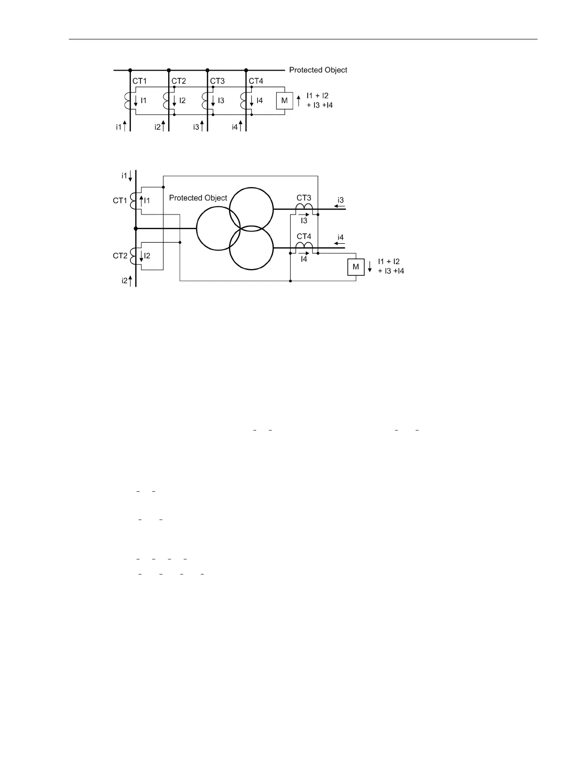
[diff-grundprinzip4enden-020926-rei, 1, en_GB]
Figure 2-18 Basic principle of differential protection for four ends (single-phase illustration)
[diff-grundprinzip-3-wickltrans-1ph-020926-st, 1, en_GB]
Figure 2-19 Basic principle of differential protection for 4 measuring locations — example of a three-
winding power transformer with 4 measuring locations (single-phase illustration)
Current Restraint
When an external fault causes a heavy current to flow through the protected zone, differences in the magnetic
characteristics of the current transformers CT1 and CT2 (Figure 2-17) under conditions of saturation may
cause a significant current flow through the measuring element M. If it is greater than the respective pickup
threshold, the device can trip even though no fault occurred in the protected zone. Current restraint (stabilisa-
tion) prevents such erroneous operation.
In differential protection systems for protected objects with two terminals, a restraining quantity is normally
derived from the current difference |
Ι
1
– Ι
2
| or from the arithmetical sum |Ι
1
| + |Ι
2
|. Both methods are equal in
the relevant ranges of the stabilisation characteristics. For protected objects with more than two ends, such as
multi-winding transformers, busbars etc, only the arithmetical sum method is possible. The latter method is
used in 7UT6x for all protected objects. The following definitions apply for 2 measuring points:
a tripping or differential current
Ι
diff
= |
Ι
1
+ Ι
2
|
and the stabilisation or restraining current
Ι
stab
= |Ι
1
| + |Ι
2
|
The current sum definition is extended for more than 2 measurement locations, e.g. for 4 measuring locations
(Figure 2-18 or Figure 2-19), therefore:
Ι
diff
= |
Ι
1
+ Ι
2
+ Ι
3
+ Ι
4
|
Ι
stab
= |Ι
1
| + |Ι
2
| + |Ι
3
| + |Ι
4
|
Ι
diff
is derived from the fundamental frequency current and produces the tripping effect quantity, Ι
stab
counter-
acts this effect.
To clarify the situation, three important operating conditions with ideal and matched measurement quantities
are considered.
Functions
2.2 Differential Protection
SIPROTEC 4, 7UT6x, Manual 93
C53000-G1176-C230-5, Edition 09.2016
 Loading...


