Jumper Settings Input/Output Board B-I/O-2
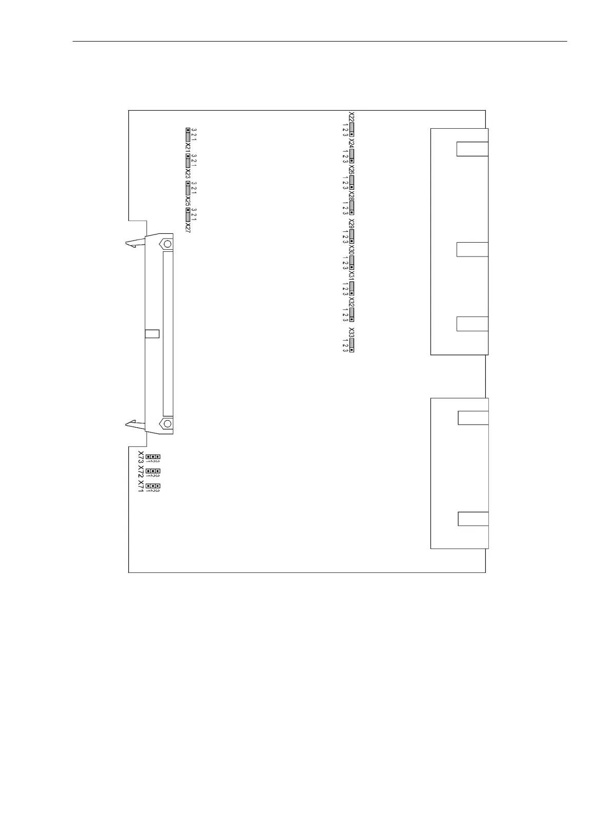
The layout of the PCB for the input/output module B–I/O–2 is illustrated in Figure 3-18.
[aufsicht-b-io-2-020313-kn, 1, en_US]
Figure 3-18
B-I/O-2 input/output board with representation of the jumpers required for checking configura-
tion settings
The selected pickup voltages of the binary inputs BI8 to BI20 (with housing size
1
/
2
) are checked according to
Table 3-20. BI8 to BI33 (with housing size
1
/
1
) are checked according to Table 3-21.
Figure 3-6 and Figure 3-77 illustrate the assignment of the binary inputs to the module slot.
Mounting and Commissioning
3.1 Mounting and Connections
SIPROTEC 4, 7SJ62/64, Manual 393
C53000-G1140-C207-8, Edition 08.2016

 Loading...


