Pickup Voltages of BI8 to BI20 for 7SJ642*-
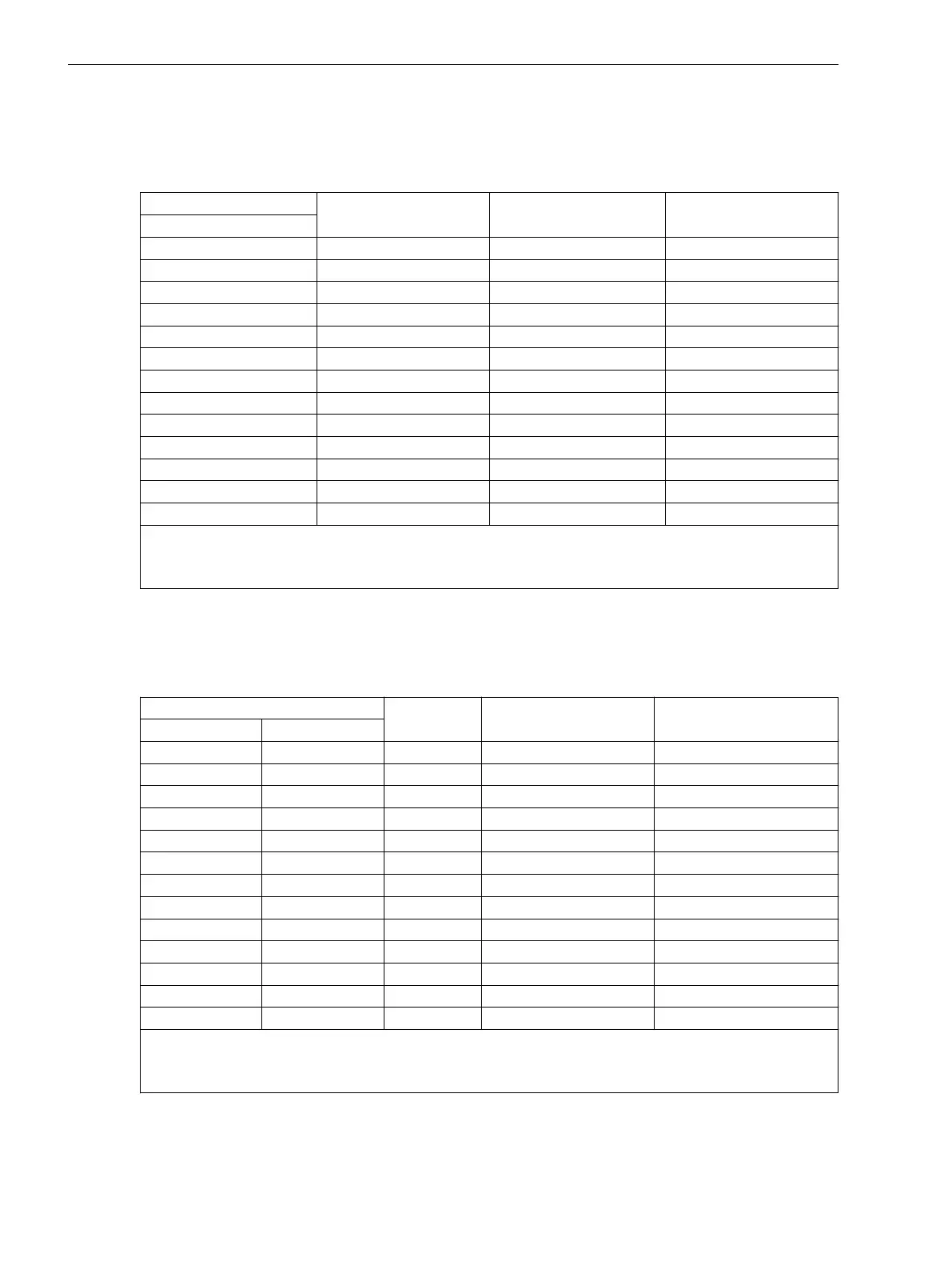
Table 3-20 Jumper settings for the Pickup Voltages of the binary inputs BI8 to BI20 on the input/output
board B–I/O-2 for model 7SJ642*-... (housing size
1
/
2
)
Binary Inputs Jumper
DC 19 V Pickup
1)
DC 88 V Pickup
2)
Slot 19
BI8 X21 1-2 2-3
BI9 X22 1-2 2-3
BI10 X23 1-2 2-3
BI11 X24 1-2 2-3
BI12 X25 1-2 2-3
BI13 X26 1-2 2-3
BI14 X27 1-2 2-3
BI15 X28 1-2 2-3
BI16 X29 1-2 2-3
BI17 X30 1-2 2-3
BI18 X31 1-2 2-3
BI19 X32 1-2 2-3
BI20 X33 1-2 2-3
1)
Factory settings for devices with power supply voltages of DC 24 V to 125 V
2)
Factory settings for devices with power supply voltages of DC 110 V to 220 V and AC 115 V or 115 V to 230
V
Control Voltage of BI8 through BI33 for 7SJ645*- and 7SJ647*-
Table 3-21
Jumper settings for the pickup voltages of the binary inputs BI8 to BI33 on the input/output
board B–I/O-2 for model 7SJ645*-... (housing size
1
/
1
)
Binary Inputs Jumper
DC 19 V Pickup
1)
DC 88 V Pickup
2)
Slot 33 left side Slot 19 right side
BI8 BI21 X21 1-2 2-3
BI9 BI22 X22 1-2 2-3
BI10 BI23 X23 1-2 2-3
BI11 BI24 X24 1-2 2-3
BI12 BI25 X25 1-2 2-3
BI13 BI26 X26 1-2 2-3
BI14 BI27 X27 1-2 2-3
BI15 BI28 X28 1-2 2-3
BI16 BI29 X29 1-2 2-3
BI17 BI30 X30 1-2 2-3
BI18 BI31 X31 1-2 2-3
BI19 BI32 X32 1-2 2-3
BI20 BI33 X33 1-2 2-3
1)
Factory settings for devices with power supply voltages of DC 24 V to 125 V
2)
Factory settings for devices with power supply voltages of DC 110 V to 220 V and AC 115 V or 115 V to 230
V
Jumpers X71, X72 and X73 on the B–I/O-2 board serve to set up the bus address. The jumpers must not be
changed. The following two tables list the jumper presettings.
The mounting locations are shown in Figure 3-6 and Figure 3-7.
Mounting and Commissioning
3.1 Mounting and Connections
394 SIPROTEC 4, 7SJ62/64, Manual
C53000-G1140-C207-8, Edition 08.2016

 Loading...


