Functions
6-30 7SA6 Manual
C53000-G1176-C133-1
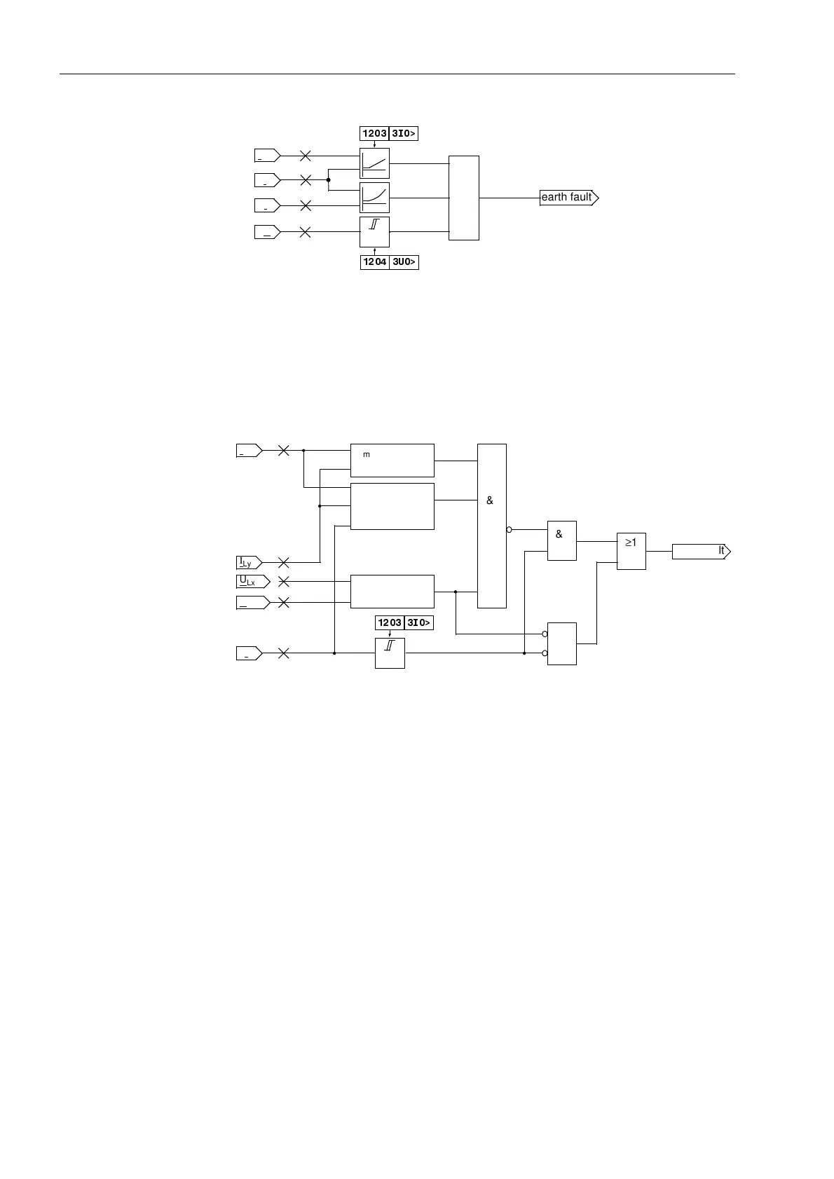
Figure 6-17 Logic of the earth fault recognition
Earth Fault
Recognition during
Single-Pole Open
Condition
The earth fault recognition is modified during the single-pole open condition with
single-pole automatic reclosure in an earthed system (Figure 6-18). In this case, the
magnitudes of the currents and voltages are monitored in addition to the angles
between the currents.
Figure 6-18 Earth fault recognition during single-pole open condition
Earth Fault
Detection
for Non-Earthed
Systems
In non-earthed systems (isolated system star point or resonant-earthed by means of
a Peterson coil) the measured displacement voltage is not used for fault detection.
Furthermore, in these systems a simple earth fault is assumed initially in case of a sin-
gle-phase fault and the fault detection is suppressed in order to avoid an erroneous
pickup as a result of the earth fault initiation transients. After a time delay 7,
3+$6,which can be set, the fault detection is released again; this is necessary for
the distance protection to still be able to detect a double earth fault with one base point
on a dead-end feeder.
If, however, an earth fault is already present in the system, it is detected by the
displacement voltage detection (8!&203,62/). In this case, there is no delay
time: an earth fault now occurring in a different phase can only be due to a double
earth fault. If, apart from the displacement measurement (8!&203,62/), there
is a fault detection in more than one phase, this is also rated as a double earth fault.
In this way, double earth faults can be detected even if no or only little earth current
flows via the measuring point.
3I
0
3I
2 3I
2
≥1
3U
0
3I
0
I
Ph
3I
0
3V0>
I
Ph
,!
8!
earth fault
&
&
≥1
max(I
Lx
, I
Ly
)<
2·min(I
Lx
, I
Ly
)
max(U
Lx
, U
Ly
)<
1.5·min(U
Lx
, U
Ly
)
Angle criteria
3I
0
>
,!
&
3I
0
I
Lx
earth fault
I
Ly
U
Lx–E
U
Ly–E
for load condition

 Loading...


