Functions
6-42 7SA6 Manual
C53000-G1176-C133-1
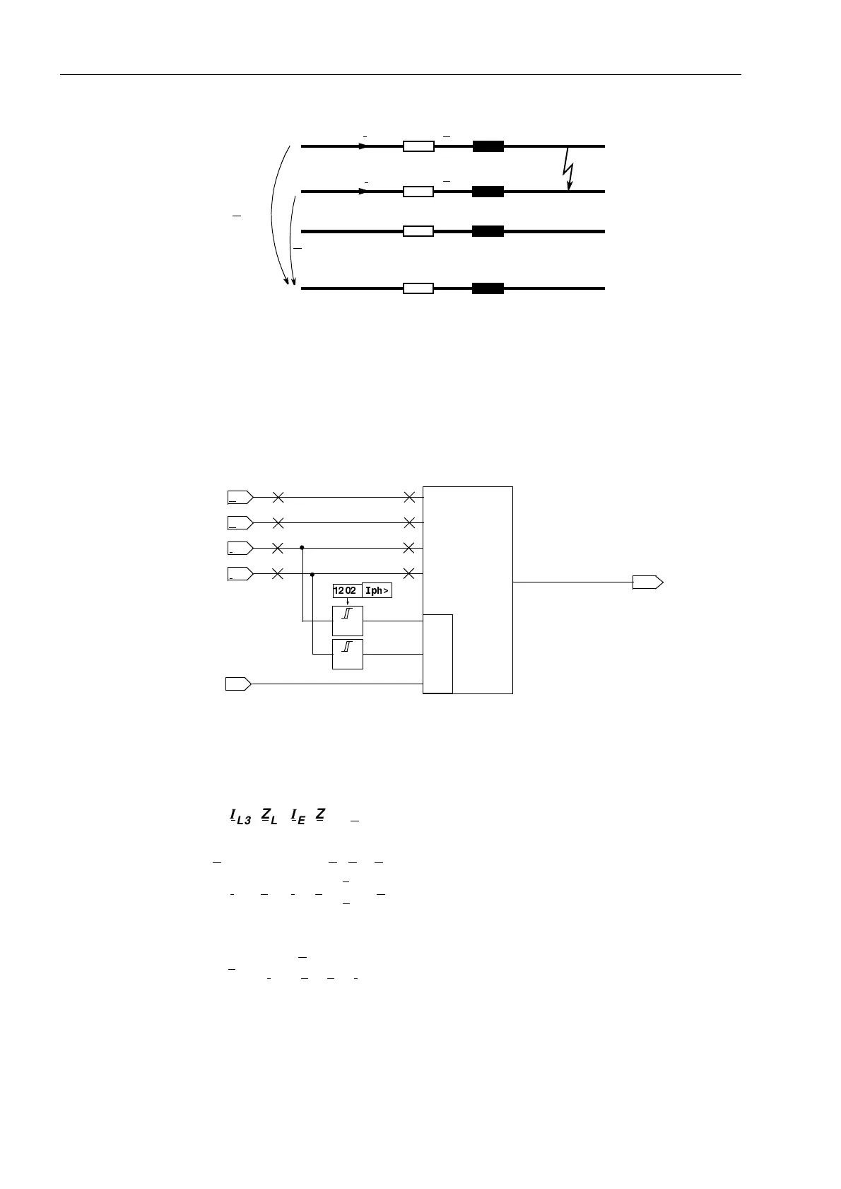
Figure 6-22 Short circuit of a phase-phase loop
The calculation of the phase-phase loop does not take place as long as one of the
concerned phases is switched off (during single-pole dead time), to avoid an incorrect
measurement with the undefined measured values existing during this state. A state
recognition (refer to Section 6.20) provides the corresponding block signal. A logic
block diagram of the phase-phase measuring system is shown in Figure 6-23.
Figure 6-23 Logic of the phase-phase measuring system
Phase–Earth Loops For the calculation of the phase-earth loop, for example during a L3–E short-circuit
(Figure 6-24) it must be noted that the impedance of the earth return path does not
correspond to the impedance of the phase. In the loop equation
Z
E
is replaced by (Z
E
/Z
L
)·Z
L
and the result is:
From this the line impedance can be extracted
I
L1
I
L2
Z
L
Z
L
L1
L2
L3
E
U
L2–E
U
L1–E
I
Lx
I
Ly
I
Lx
>
I
Ly
>
&
Measuring
System
L
x
–L
y
from state
recognition
R
x–y
; X
x–y
U
Lx
U
Ly
,SK!
I
L3
Z
L
I
E
Z
E
U
L3–E
=
⋅
–
⋅
I
L3
Z
L
I
E
Z
L
Z
E
Z
L
-------
U
L3–E
=
⋅⋅
–
⋅
Z
L
U
L3–E
I
L3
Z
E
Z
L
⁄ I
E
⋅–
------------------------------------------
=

 Loading...


