Functions
6-437SA6 Manual
C53000-G1176-C133-1
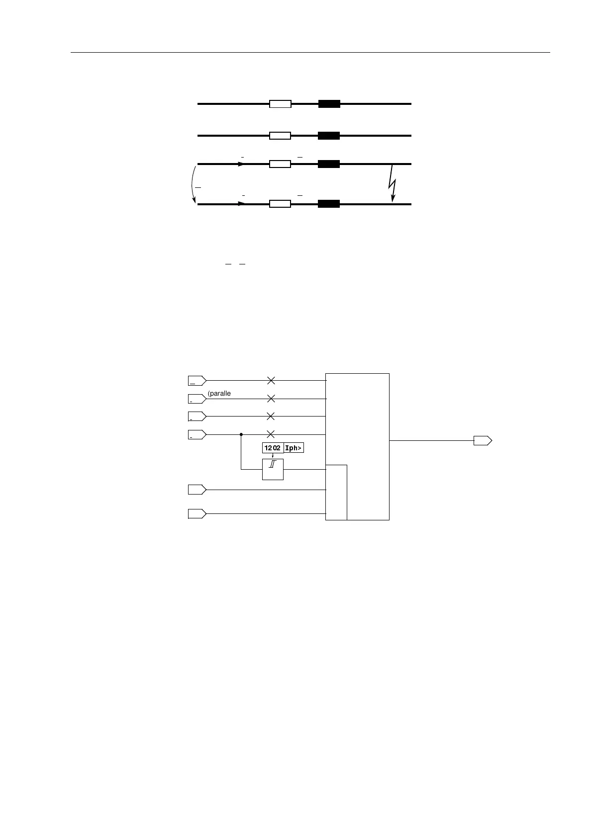
Figure 6-24 Short circuit of a phase-earth loop
The factor Z
E
/Z
L
only depends on the line parameters and no longer on the fault
distance.
The evaluation of the phase-earth loop does not take place as long as the affected
phase is switched off (during single-pole dead time), to avoid an incorrect
measurement with the undefined measured values existing in this state. A state
recognition (refer to Section 6.20) provides the corresponding block signal. A logic
block diagram of the phase-earth measuring system is shown in Figure 6-25.
Figure 6-25 Logic of the phase-earth measuring system
Unfaulted Loops The above considerations apply to the relevant short-circuited loop. A pick-up with the
current-based fault detection modes (I, U/I, U/I/ϕ) guarantees that only the faulty
loop(s) are released for the distance calculation. In the impedance pick-up, however,
all six loops are calculated, the impedances of the healthy loops are also influenced
by the fault currents and voltages in the short-circuited phases. During a L1–E fault for
example, the fault current in phase L1 also appears in the measuring loops L1-L2 and
L3-L1. The earth current is also measured in the loops L2–E and L3–E. Combined with
load currents which may flow, the unfaulted loops produce the so-called “apparent
impedances“, which have nothing to do with the actual fault distance.
These “apparent impedances” in the unfaulted loops are usually larger than the short-
circuit impedance of the faulted loop because the unfaulted loop only carries a part of
the fault current and always has a higher voltage than the faulted loop. For the
selectivity of the zones, the “apparent impedances” are therefore of no consequence.
I
L3
I
E
Z
L
Z
E
L1
L2
L3
E
U
L3–E
I
Lx
I
E
I
Lx
>
&
measuring
syst.
L
x
–E
from state
recognition
R
x–E
; X
x–E
U
Lx
I
EP
earth fault
recognition
,SK!
(parallel line)

 Loading...


