Functions
6-208 7SA6 Manual
C53000-G1176-C133-1
J
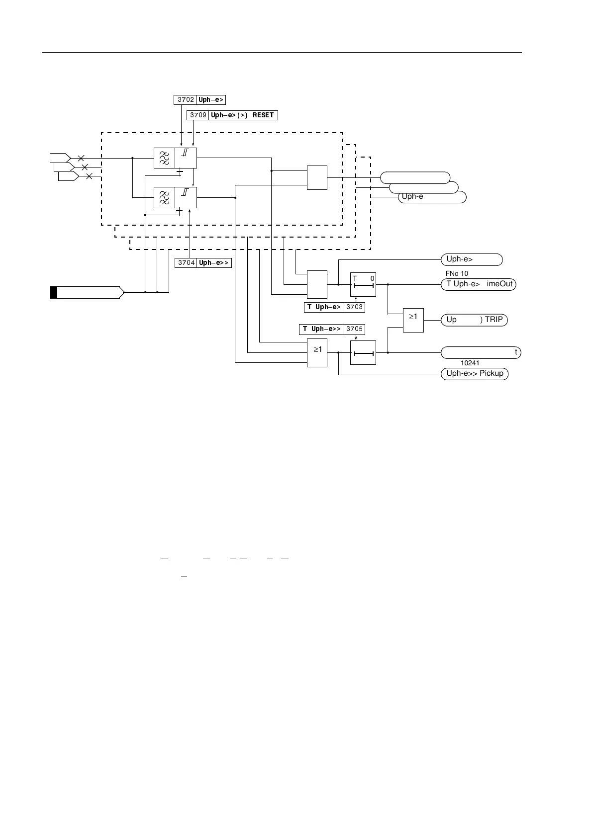
Figure 6-105 Logic diagram of the overvoltage protection for phase voltages
Overvoltage
Phase–Phase
The phase–phase overvoltage protection operates just like the phase–earth
protection except that it detects phase–to–phase voltages. Accordingly, phase–to–
phase voltages which have exceeded one of the stage thresholds 8SKSK! or 8SK
SK!!are also indicated. Otherwise, Figure 6-105 also applies in principle.
The phase–phase overvoltage protection can also be blocked via a binary input
“!8SKSK!!%/.”.
Overvoltage
Positive Sequence
System U
1
The device calculates the positive sequence system voltage according to its defining
equation:
U
1
=
1
/
3
⋅(U
L1
+ a⋅U
L2
+ a
2
⋅U
L3
)
with a
= e
j120°
.
The resulting single–phase AC voltage is fed to the two threshold stages 8! and
8!! (see Figure 6-106). Combined with the associated time delays these stages
form a two-stage overvoltage protection for the positive sequence system. Here too,
the drop-off to pick-up ratio can be set.
The overvoltage protection for the positive sequence system can also be blocked via
a binary input “!8!!%/.”.
U
L3-E
U
L2-E
U
L1-E
U>
8SK²H!
T0
78SK²H!
T Uph-e> TimeOut
Uph-e> Pickup
L1
U>>
8SK²H!!5(6(7
≥1
≥1
T0
78SK²H!!
T Uph-e>> TimeOut
Uph-e>> Pickup
≥1
Uph-e>(>) TRIP
≥1
Uph-e>(>) PU L3
Uph-e>(>) PU L2
Uph-e>(>) PU L1
L2
L3
8SK²H!!
>Uph-e>(>) BLK
FNo 10201
FNo 10242 to 10244
FNo 10240
FNo 10241
FNo 10245
FNo 10247
FNo 10246

 Loading...


