7SA6 Manual
C53000-G1176-C133-1
The state where both binary inputs are not energized (“L”) is only present
during a short transition phase (trip relay contact is closed, but the circuit
breaker has not yet opened) if the trip circuit is healthy.
A continuous occurrence of this state is only possible during interruption
or short circuit of the trip circuit as well as during failure of the battery
supply voltage, or faults in the mechanism of the circuit breaker.
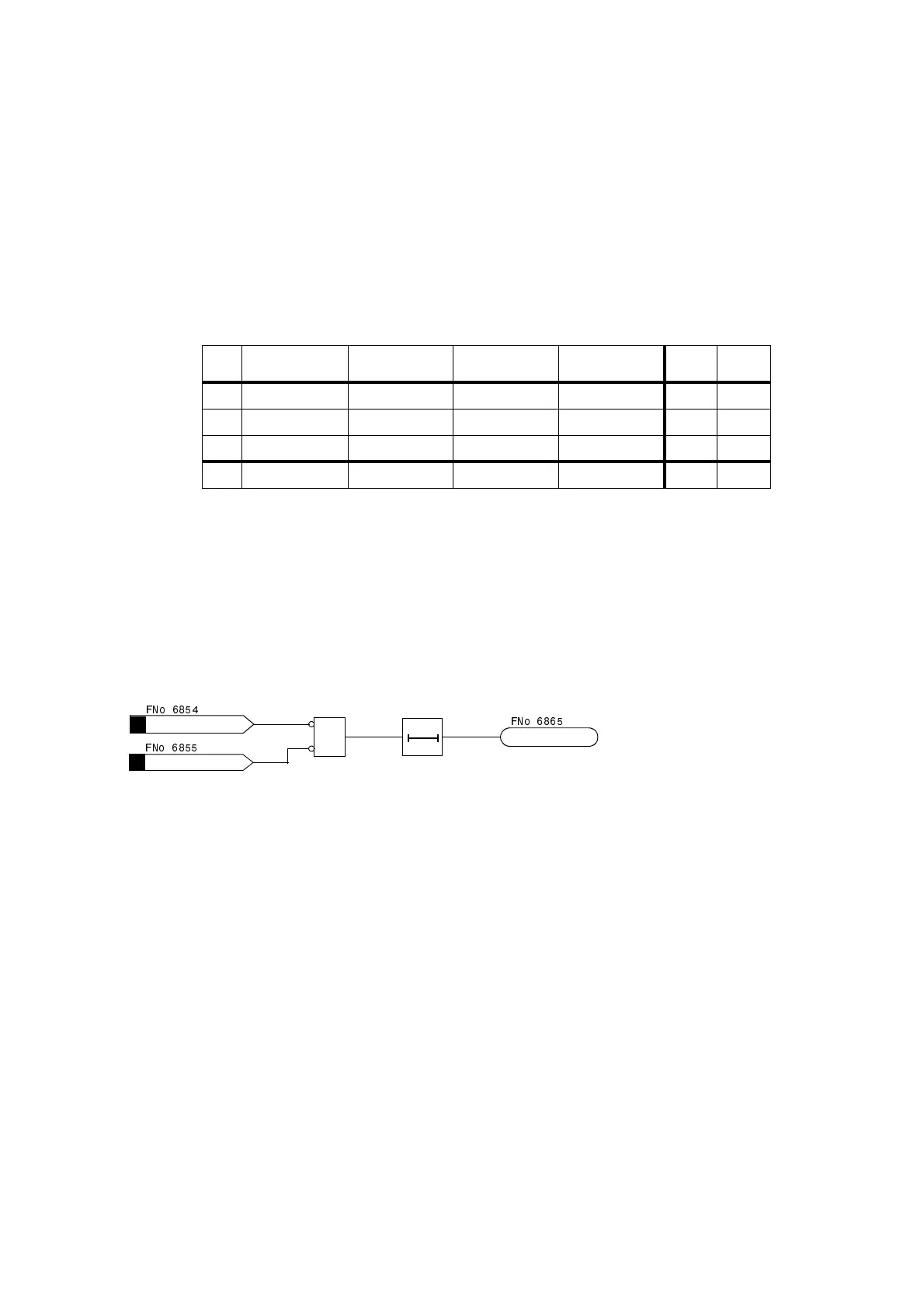
The two binary inputs are periodically interrogated to determine their
state. An interrogation takes place every 500 ms. Only once n = 3
sequential state interrogations detect a failure, will the failure alarm be
generated (refer to Figure 6-135). Due to this measurement repetition the
delay of the failure alarm is determined. A failure alarm due to transient
transition phases is thereby avoided. After removal of the failure in the
trip circuit, the alarm automatically resets after the same time.
Figure 6-135 Logic diagram of the trip circuit supervision with two binary inputs
Supervision Using
One Binary Input
The binary input is connected in parallel to the corresponding trip relay of
the protection according to Figure 6-136. The circuit breaker auxiliary
contact is bridged by means of a high-ohmic shunt resistor R.
The control voltage of the circuit breaker should be at least twice the
minimum voltage drop across the binary input (U
C
> 2·U
BImin
). As at least
19 V are required for the binary input, the supervision function can be
used if the trip control voltage is greater than approximately 38 V.
An calculation example for the substitute resistance of R is shown in
subsection 8.1.2, margin “Trip Circuit Supervision”.
Table 6-11 Condition table of the binary inputs depending on the trip relay state and
CB state
No. Trip
relay
Circuit
breaker
Auxiliary
contact 1
Auxiliary
contact 2
BI 1 BI 2
1 open CLOSED closed open H L
2 open OPEN open closed H H
3 closed CLOSED closed open L L
4 closed OPEN open closed L H
&
>TripC1Tr.Rel
>TripC1Br.Rel
TT
T approx. 1 to 2 s
FAIL: Trip cir.
)1R
)1R
)1R

 Loading...


