Control During Operation
7-477SA6 Manual
C53000-G1176-C133-1
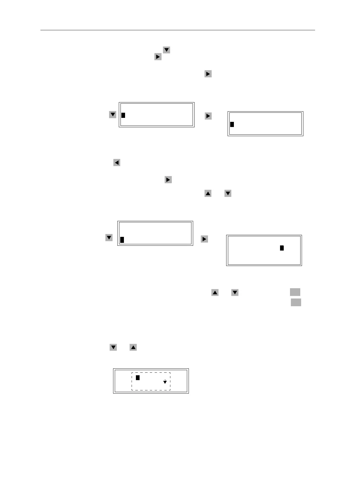
Select, by means of the key, the item %UHDNHU6ZLWFK, and continue with the
item by pressing the key. The selection %5($.(56:,7&+ appears. See Figure
7-45.
Select'LVSOD\ (default) and press the key. The selection ',63/$< appears, in
which the positions of all planned switching devices can be read out.
Figure 7-45 Display of Switch Positions in the HMI (example)
The key can be used to return to %5($.(56:,7&+.
To control a switching device, select the option &RQWURO in the %5($.(56:,7&+
sub-menu and press the key to go to the table of operating resources that can be
controlled. See Figure 7-46. All planned switching devices appear. The actual position
of each switch is displayed first. Use the and keys to move to the desired
switch.
Figure 7-46 Control of Switching Devices from the Operator Control Panel (example)
Select the switch to be controlled using the and keys and press the key.
Enter Password No. 1 (for interlocked switching) and acknowledge with the key.
Note: if the switching mode is 12 1²,17(5/2&.('7HVW (Sub-section 7.4.7), all
switching operations are only possible with Password No. 2 (for non-interlocked
switching).
A new window appears. Depending on the operating and command type of the
selected switching device, various options are offered. Move between them using
the and keys.
Figure 7-47 Selection Window for Control Operations on the Front Panel (example)
',63/$<
!%UHDNHU23(1
!'LVF6ZLW&/26
%5($.(56:,7&+
!'LVSOD\²!
!&RQWURO²!
%5($.(56:,7&+
!'LVSOD\²!
!&RQWURO²!
&21752/
%UHDNHU!&/26
'LVF6ZLW&/26
*QG6ZLW2))
ENTER
ENTER
&2175
!23(1
36!&/26(21
7UH(VFDSH21

 Loading...


