Control During Operation
7-537SA6 Manual
C53000-G1176-C133-1
The Interlock display has an object table similar to the one described for Set Status.
The table provides the set interlocking conditions, which prevent, or could prevent, a
local control operation. Letters identify the interlocking conditions. The meanings of
the letters are:
• L Local/Remote (Switching Authority),
• S Equipment is subject to System Interlocking (in Substation Controller).
Commands entered locally are sent to the central computer or controller,
• Z Zone controlled (Field- or Bay-Interlocking),
• P Check switch position (test actual vs. scheduled),
• B Blocking by picked-up protection elements,
• – Non-Interlocked.
From PC with
DIGSI
®
4
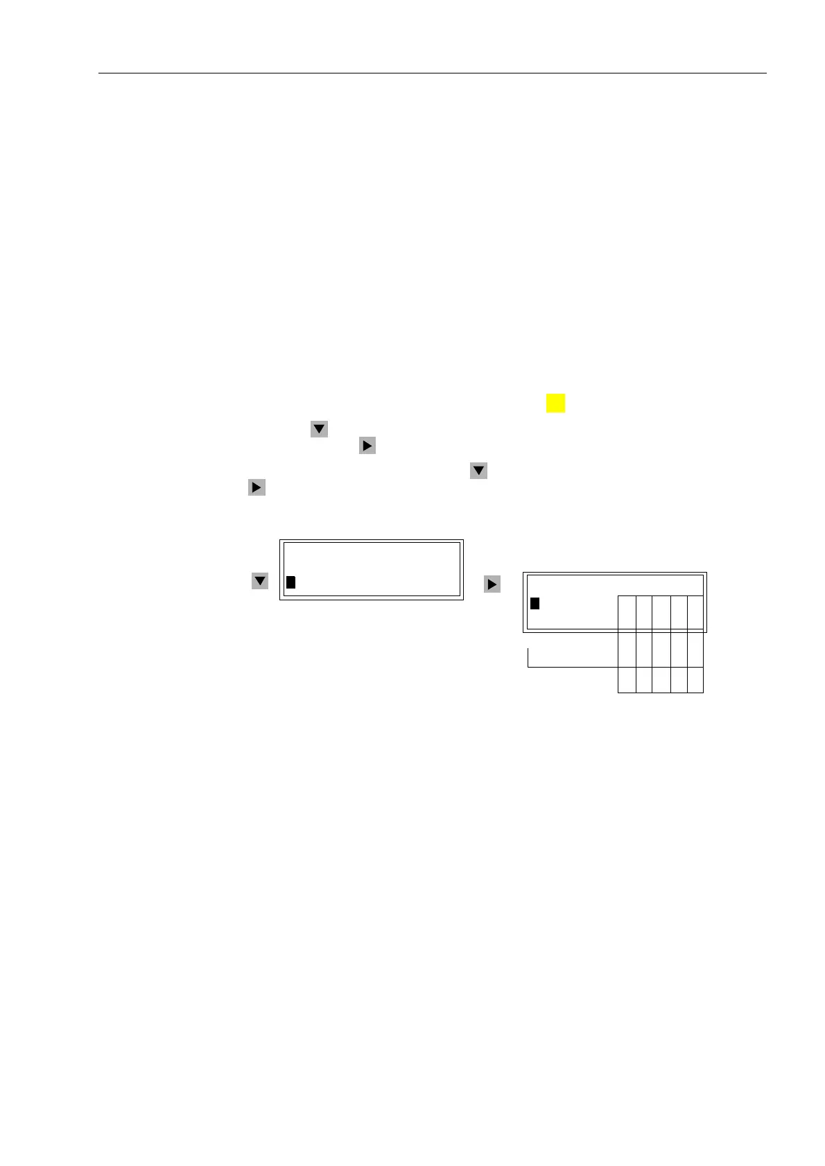
With a device ready for operation, first press the key. The 0$,10(18 appears.
Using the key, select the menu item &RQWURO and move to editing the control
functions with the key. The selection &21752/ appears.
Select the item ,QWHUORFN with the key and switch to the next selection using the
key. The selection ,17(5/2&. appears. See Figure 7-53.
Figure 7-53 Example of Interlocking Conditions for Switching Equipment, Front Panel
From PC with
DIGSI
®
4
Interlocking is set for each switching device during project planning (see Sub-section
5.2.4) using the matrix and the dialog box “Object Properties”. Readout of the actively
set interlocking is always possible, across the entire path, without a password.
If the 2QOLQH window in DIGSI
®
4 is opened with a double click, the operating
functions for the device appear in the left part of the window (Figure 7-36). Double
clicking on 6HWWLQJV brings up the function selection in the right side of the window.
By double clicking on 0DVNLQJ,2, the matrix is opened. Mark the switching device
(in the line for the operating message of the switching device). Using the
right
mouse
key, the properties of the switching device can now be called up. The conditions for
,QWHUORFN6ZLWFKLQJ, among other items, are recognizable in the dialog box that
opens. Active test conditions are identified with a check mark.
:
MENU
,17(5/2&.
!%UHDNHU/²=3%
!'LVF6ZLW/²=3%
&21752/
!7DJJLQJ²!!
!,QWHUORFN²!
1. 2. 3. 4. 5.
*QG6ZLW/²=3%
:

 Loading...


