Installation and Commissioning
8-277SA6 Manual
C53000-G1176-C133-1
Input/Output Board
C–I/O–11
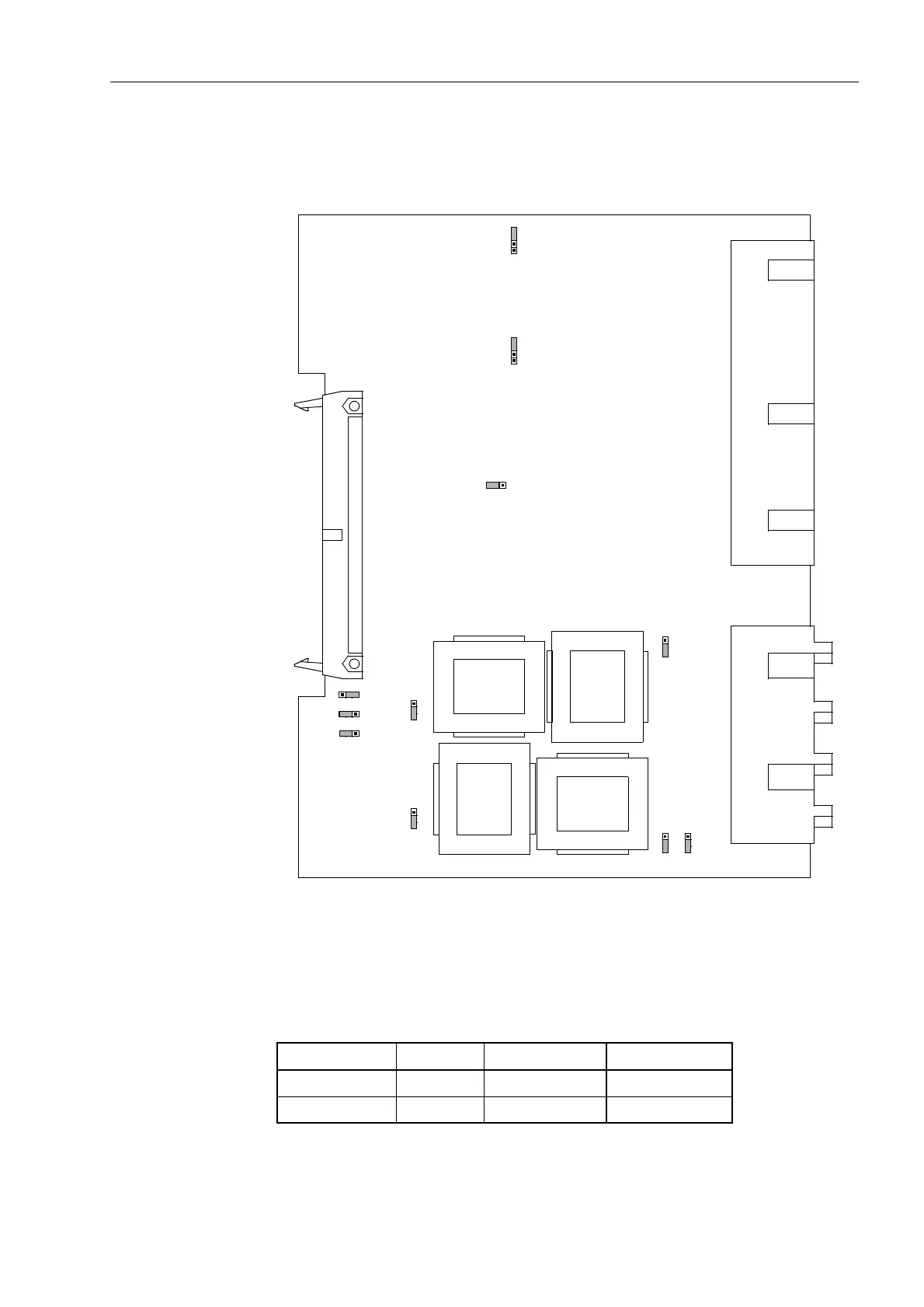
The layout of the printed circuit board for the input/output board C-I/O–11 is illustrated
in Figure 8-15.
Figure 8-15 The input/output board C-I/O–11 with the jumpers necessary for the control
of settings.
Table 8-15 Jumper setting of control voltages of the binary inputs BI6 and BI7 on the
binary input/output boards C– I/O–11
1
) Factory settings for devices with power supply voltages of 24 VDC to 125 VDC
2
) Factory settings for devices with power supply voltages of 110 VDC to 220 VDC and 115 VAC
Binary Inputs
Jumper
Threshold 17 V
1
) Threshold 73 V
2
)
BI6 X21 L M
BI7 X22 L M
T8
T10
T11
T9
X60
(AD2)
L
X62
1A 5A
123
X63
1A 5A
123
X61
1A 5A
123
X64
1A 5A
123
X65
IEE IE
X73
1
2
3
(AD1)
X72
1
2
3
(AD0)
X71
H
1A
5A
1
2
3
X21
1
X22
1
LMH LMH

 Loading...


