Installation and Commissioning
8-297SA6 Manual
C53000-G1176-C133-1
Input/Output Board
B–I/O–2
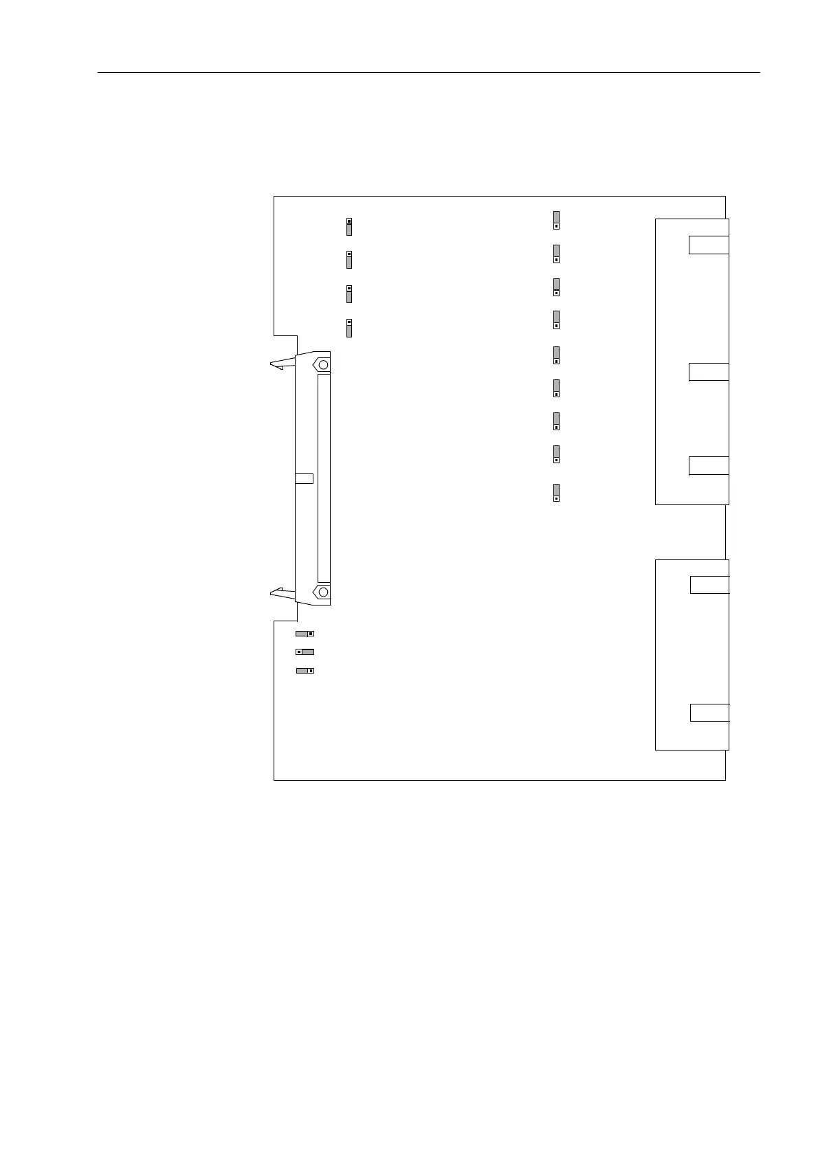
The layout of the printed circuit board for the input/output board B–I/O–2 is illustrated
in Figure 8-16.
Figure 8-16 The input/output board B–I/O–2 with the jumpers necessary for the setting
check
Check for control voltages of binary inputs:
BI8 to BI20 (for housing size
1
/
2
) according to Table 8-17.
BI8 to BI33 (for housing size
1
/
1
) according to Table 8-18.
123
X21
123
X23
123
X25
123
X27
321
X22
321
X24
321
X26
321
X28
321
X29
321
X30
321
X31
321
X32
321
X33
X73
1
2
3
X72
1
2
3
X71
1
2
3

 Loading...


