Installation and Commissioning
8-337SA6 Manual
C53000-G1176-C133-1
Serial Interfaces
with Bus Capability
Using interfaces with bus capability requires a termination of the last device at the bus,
i. e. terminating resistors must be switched to the line. Talking about the 7SA6 this
refers to the version with the RS485 interface or the Profibus interfaces.
The terminating resistors are located on the RS485 interface module or the Profibus
interface module that is mounted to the processor input/output board C–CPU–2 (å in
Figure 8-8 to 8-10) or located directly on the latter (see also Subsubsection 8.1.3.3,
“Processor Board C-CPU-2”, and Table 8-6).
Figure 8-17 shows the printed circuit board of the C–CPU–2 and the order the
modules are mounted.
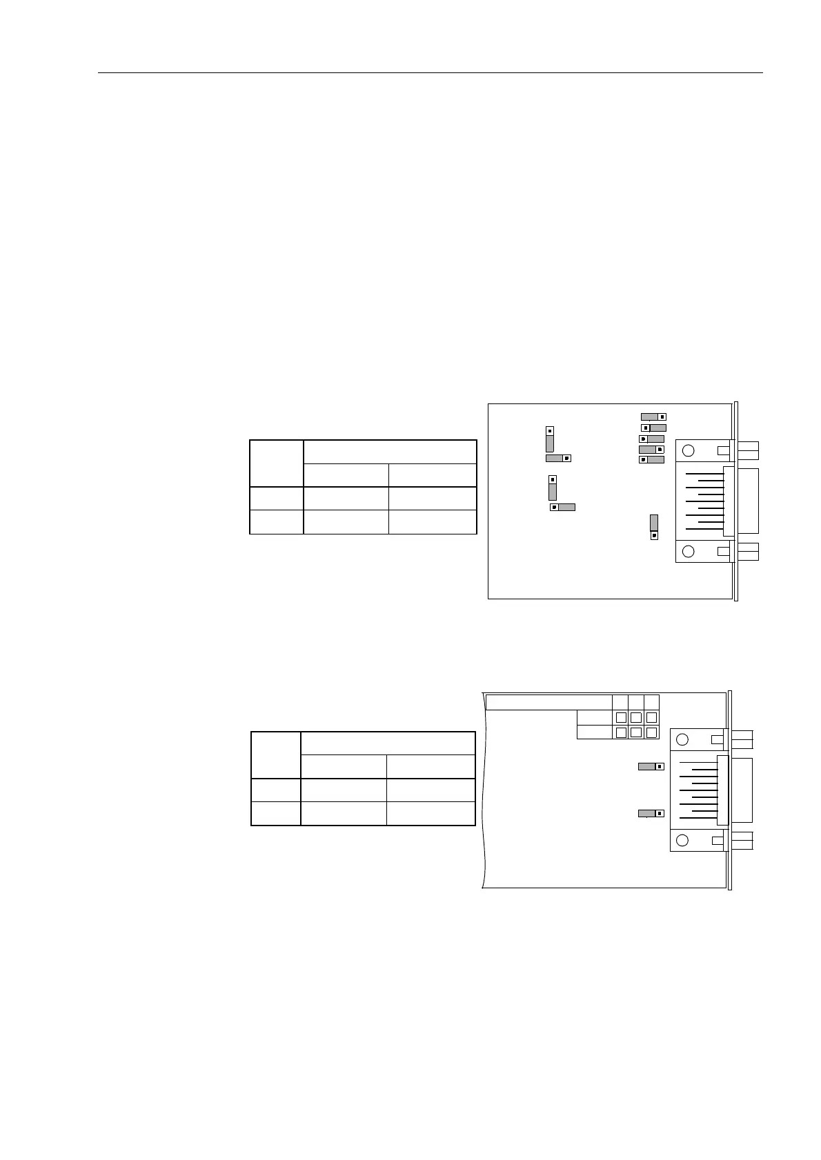
The module for the RS485 interface is illustrated in Figure 8-18 for Profibus in
Figure 8-19.
The jumpers are preset in such a way that the terminating resistors are disconnected.
The two jumpers of a module must always be plugged in the same way.
Figure 8-18 Location of the jumpers for the configuration of terminating resistors of the
RS 485 interface
Figure 8-19 Location of the jumpers for the configuration of terminating resistors of the
Profibus interface
The terminating resistors can also be connected externally (e.g. to the connection
module) as illustrated in Figure 8-12. In this case, the terminating resistors located on
the RS485 or the Profibus interface module or the resistors located directly on the
processor circuit board C–CPU–2 must be disconnected.
X3
132
X10
132
8X
1
3
2
X12
132
C53207-
A324-B180
1
3
2
X11
X6
X7
X4
X5
132
1
3
2
X13
Jumper
Terminating Resistors
Connected Disconnected
X3 2-3 1-2*
)
X4 2-3 1-2*
)
*
)
Factory Set
X3
312
X4
312
Jumper
Terminating Resistors
Connected Disconnected
X3 1-2 2-3
X4 1-2 2-3
C53207-A322-
234
B100
B101

 Loading...


