HRX-OM-X037
Chapter 5 Display and Setting of Various Functions
5.4 Description of the Screen
HRL Series
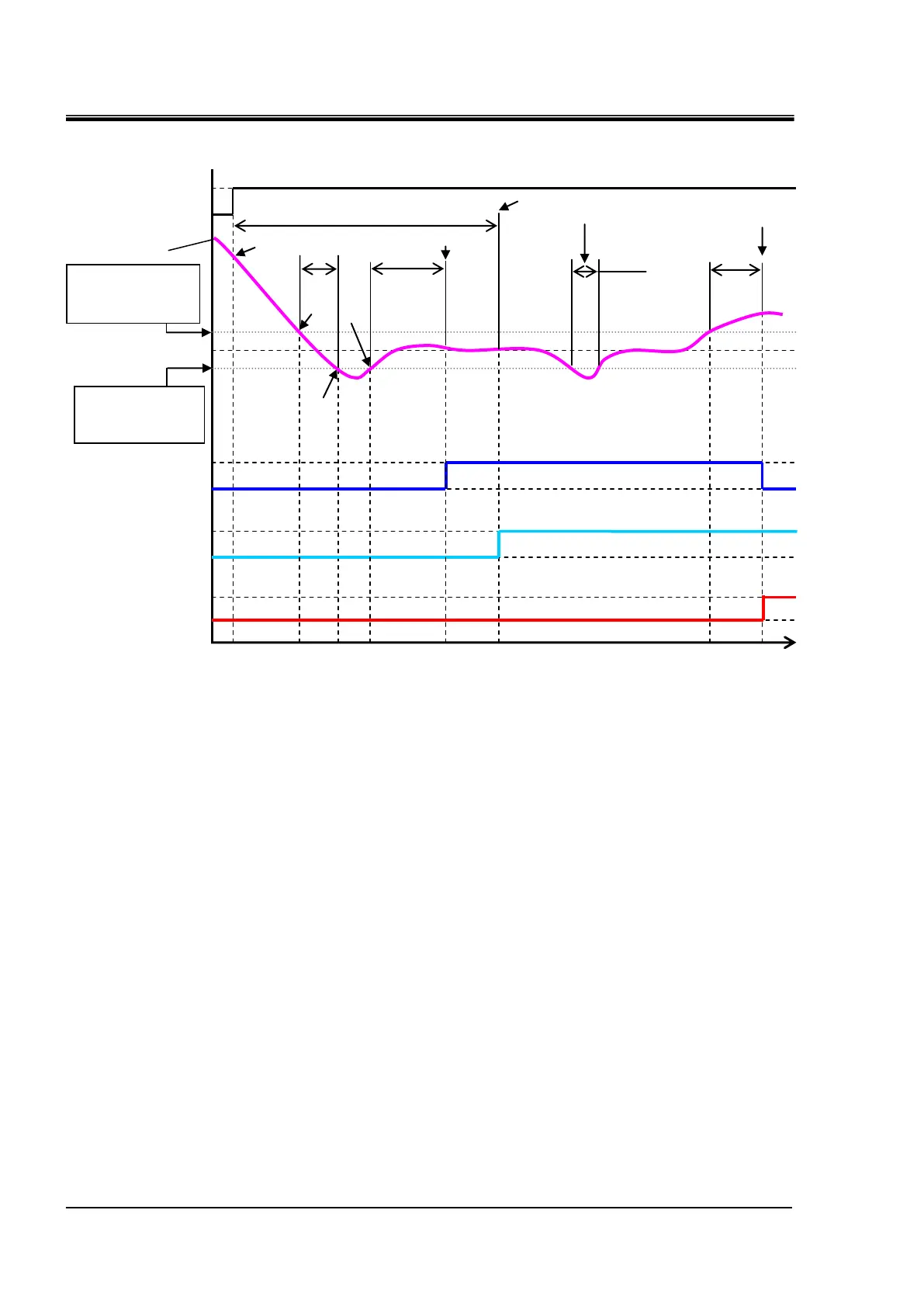
Fig. 5-6 TEMP READY signal chart
Status (1): Start operation of the chiller.
Status (2): The temperature is in the "High/Low” range, but no “TEMP READY” signal is generated
since “Ready Time” is set at 300 sec at this point.
Status (3): The 300 sec count for “Ready Time” is reset since the temperature is now outside of the
“Low” range.
Status (4): The 300 sec count for “Ready Time” starts since the temperature is now within the
“High/Low” range.
Status (5): “TEMP READY” signal is generated at this point since the temperature remains in the
“High/Low” range for 300 sec of “Ready Time.”
Monitoring of “TEMP READY alarm (AL12)” does not start since “Start Time” is set at
1000 sec.
Status (6): Monitoring of “TEMP READY alarm (AL12)” starts at this point where 1000 sec of “Start
Time” has elapsed.
Status (7): “TEMP READY” signal output continues since the temperature is now back within the
“Out Time” range of 200 sec even though it was temporarily outside the “Low” range.
Status (8): “TEMP READY” signal turns OFF when 200 sec has passed after the temperature rises
above the “High” range. “TEMP READY alarm (AL12)” is simultaneously activated.
Circulating fluid set
temperature 20ºC
Circulating fluid
temperature
TEMP READY
Alarm (AL12)
monitoring
“High” Upper
Temperature limit
+2C
“Low” Lower
temperature limit
-2C

 Loading...


