HRX-OM-X037
Chapter 8 Control, Inspection and Cleaning
8.3 Operation Stop for an Extended Period of Time
HRL Series
5. Remove the DI filter.
1) Remove the maintenance panel and remove the DI filter.
(Refer to “8.4.2 Replacing the DI filter”.) Store the removed DI filter separately.
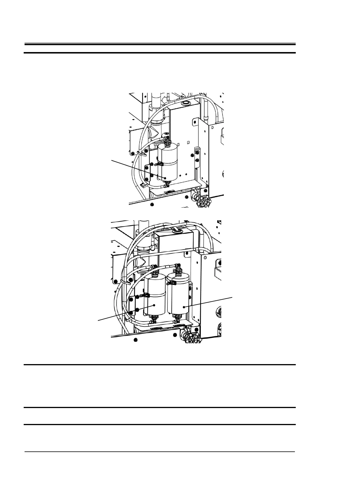
2) Install the DI filter temporary piping that was installed at the time of delivery.
Fig. 8-5 Temporary pipe installation for DI filter
Fig. 8-6 Temporary pipe installation for DI filter(For option D1)
6. After confirming that the circulating fluid has been sufficiently discharged from the product,
customer's facilities and piping, perform an air purge (pressure less than 0.1 MPa, about 1
minute) from the circulating fluid outlet of the product.
Purge both CH1 and CH2, Circulating fluid is drained from the drain port.
7. Close the ball valve after draining the circulating fluid.
8. Close the supply port cap.
Temporary piping for DI filter(CH2)

 Loading...


