HRX-OM-X037
Chapter 3 Transport and Setting Up
HRL Series 3.3 Installation
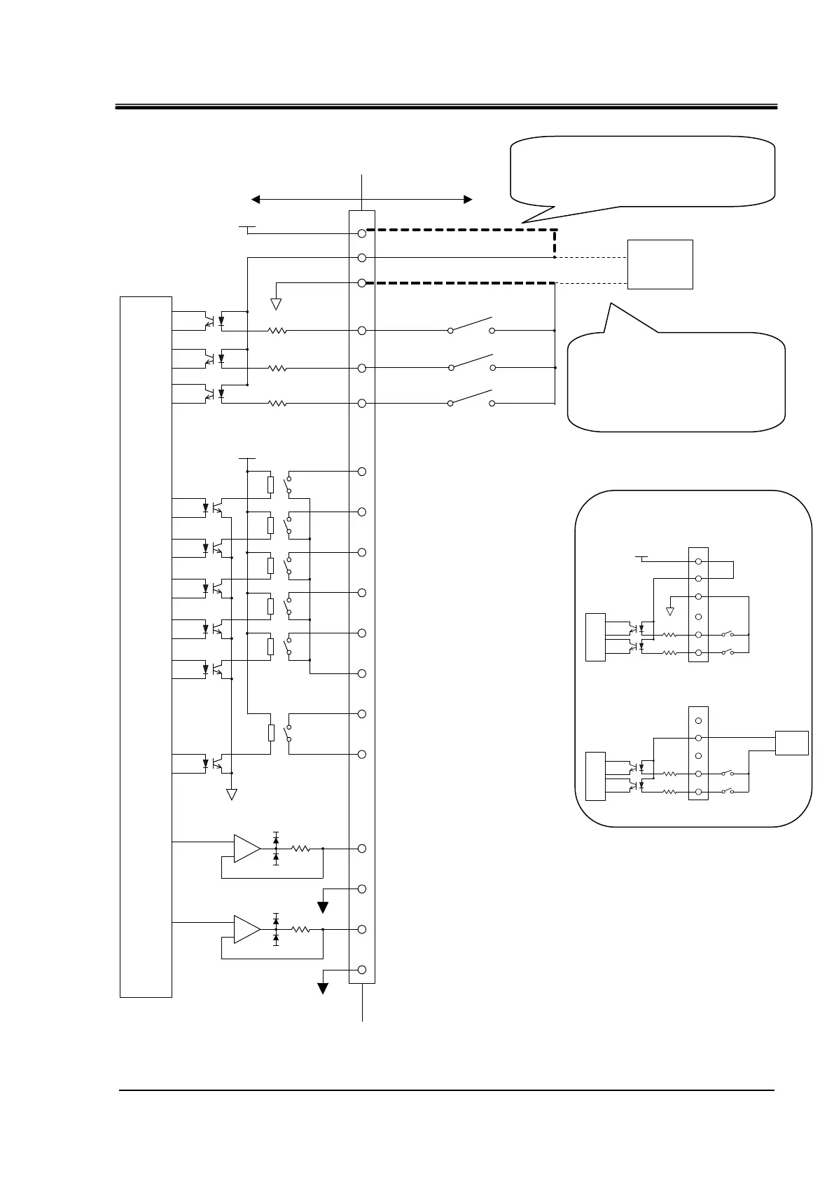
Fig. 3-11 Circuit diagram
When using this product's power supply,
connect pin 1 to pin 2 and the COM side
of each contact input signal to pin 14.
When using a customer's power
supply, connect the 24V DC +
side to pin 2 and the COM side
of each contact input signal to
the customer's power COM.
Power supply usage example
Customer power supply usage example
DC24V
1
14
3
2
1
14
3
2
Power
supply
DC24V
24COM
4
3
4
This product power supply
usage example
Analog output 1 : CH2 Circulating fluid temperature
This product side Customer system side
DC24V
+
-
-15V
100Ω
ANALOG COM
24COM
Contact output 1 : Operation status
1
24COM
DC +24V(output)
4.7kΩ
4.7kΩ
4.7kΩ
+15V
+
-
-15V
100Ω
+15V
ANALOG COM
Internal
circuit
14
3
16
4
6
19
7
20
8
15
5
18
11
23
10
22
Contact output 2 : "FLT"
Contact output 3 : "WRN"
Contact output 4 : OFF
Contact output 5 : OFF
(Momentary)
Run/Stop
Operation mode request
[When Warning alarm occurr OFF]
[When Fault alarm occurr OFF]
[Operation ON]
Contact output 6 : OFF
2
DC24V
DC +24V(input)
EXT DC24V
EXT 24COM
Power
supply
Analog output 2 : CH2 Electric conductivity
External switch
24COM(output)
Contact output 1-5 common
Contact output 6 common
Analog output1common
Analog output 2 common

 Loading...


