EasyManua.ls Logo

SMC Networks HRL100-A 40 Series

SMC Networks HRL100-A 40 Series
194 pages
To Next Page IconTo Next Page
To Previous Page IconTo Previous Page
Loading...
HRX-OM-X037
Chapter 3 Transport and Setting Up
3.3 Installation
HRL Series
3-20
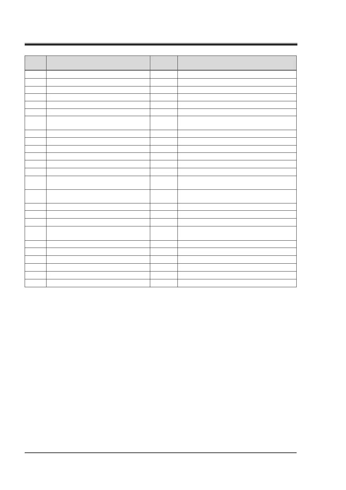
Table 3.3-4 Contact input/output communicatin /Analog output pin number
PIN
No.
Application
Division
Default setting
1
DC24V output
Output
2
DC24V input
Input
3
Contact input signal 1
Input
Run/Stop 1
4
Contact input signal 3
Input
Operation mode request signal (fix )2
5
Contact output signal 6
Output
OFF1
6
Contact output signal 1
Output
Run status signal [N.O type](fix)2
7
Contact output signal 3
Output
Operation continuation[WRN]alarm signal
[N.C. type ](fix)2
8
Contact output signal 5
Output
OFF 1
9
None
Do not connect. 3
10
Analog output signal 2
Output
CH2 Electric conductivity 1
11
Analog output signal 1
Output
CH2 Circulating fluid temperature 1
12
None
Do not connect. 3
13
None
Do not connect. 3
14
24 COM output
(Common of contact input signal)
Output
15
Common of contact output signal
1, 2, 3, 4, 5
Output
16
Contact input signal 2
Input
External switch signal 1
17
None
Do not connect. 3
18
Common of contact output signal 6
Output
19
Contact output signal 2
Output
Operation stop [FLT] alarm signal
[N.C. type ](fix)2
20
Contact output signal 4
Output
OFF 1
21
None
Do not connect. 3
22
Common of contact output signal 2
Output
23
Common of contact output signal 1
Output
24
None
Do not connect. 3
25
None
Do not connect. 3
1 : It is possible to change the setting.
2 : You can not change the setting(N.O type / N.C. type” can be changed).
3 : Do not connect any wire

Table of Contents

Related product manuals