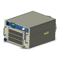
HRX-OM-X037
Contents
HRL Series
・Setting the usage time of DI filter....................................................................................................5-22
・Setting of the usage time of dustproof filter (Only for air-cooled type) ...........................................5-22
5.4.6 Software version screen .....................................................................................................5-23
5.4.7 CH1 setting screen .............................................................................................................5-23
・Temperature rise/drop alarm (AL10/AL11)......................................................................................5-24
・TEMP READY alarm (AL12) of TEMP READY function .................................................................5-26
・Offset (TEMP OFFSET) function ....................................................................................................5-29
・Pump operation mode ....................................................................................................................5-32
・Discharge pressure alarm (AL18/AL19/AL20) ................................................................................5-33
・Electric conductivity and alarm setting (AL28) ................................................................................5-35
5.4.8 CH2 setting screen .............................................................................................................5-36
・Temperature rise/drop alarm (AL14/AL15) setting ..........................................................................5-37
・TEMP READY alarm (AL16) and TEMP READY function ..............................................................5-38
・Offset (TEMP OFFSET) function ....................................................................................................5-40
・Pump operation mode ....................................................................................................................5-41
・Discharge pressure alarm (AL21/AL23/AL24/AL26) ......................................................................5-42
・Electric conductivity and alarm setting (AL27) ................................................................................5-43
5.4.9 Function setting screen ......................................................................................................5-45
・KEY-LOCK, START-UP operating method, ANTI-FREEZING and WARMING-UP ........................5-46
・Continuing pump operation .............................................................................................................5-47
・Ambient temperature alarm (AL35) and maintenance alarm (AL36) ..............................................5-50
・TEMP OUT signal ...........................................................................................................................5-51
・Data reset .......................................................................................................................................5-52
5.4.10 Communication setting screen ...........................................................................................5-53
・Setting for communication error (AL34)/contact input signal detection (AL30 and AL31) ..............5-54
・Serial communication setting ..........................................................................................................5-55
・Setting of analog output signal .......................................................................................................5-57
・Setting of contact input signal form.................................................................................................5-57
・Setting of contact output signal 1 to 3 ............................................................................................5-59
・Setting of contact output signal 4 to 6 ............................................................................................5-59
・Ethernet Modbus / TCP communication settings ...........................................................................5-64
5.4.11 How to set the IP address ..................................................................................................5-65
5.4.12 Temperature waveform screen...........................................................................................5-66
Chapter 6 Option ............................................................................... 6-1
6.1 Option-T2 [CH2 High-Pressure Pump Mounted] ................................................... 6-1
6.2 Option-T3 [CH2 High-Pressure Pump Mounted] ................................................... 6-2
Chapter 7 Alarm Notifications and Troubleshooting ...................... 7-1
7.1 Alarm Notification ................................................................................................... 7-1
7.2 Operation of this product when an alarm occurs ................................................. 7-1
7.3 Troubleshooting ...................................................................................................... 7-2
7.3.1 Alarm contents, causes, and troubleshooting ...................................................................... 7-2
7.4 Other Errors ............................................................................................................. 7-5

 Loading...


