HRX-OM-X037
Chapter 3 Transport and Setting Up
3.3 Installation
HRL Series
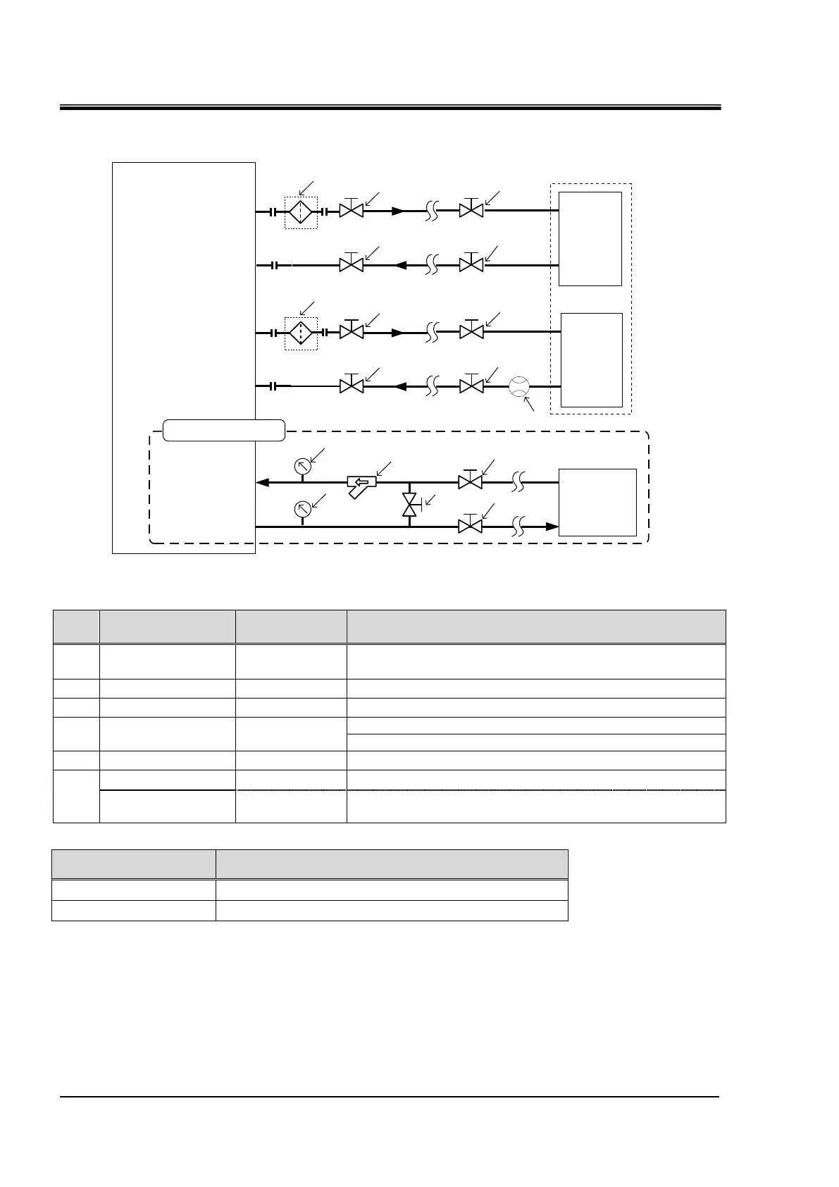
Recommended piping circuit
2
2
2
2
3
User's
equipment
4
4
4
4
Circulating fluid outlet
CH2
Circulating fluid return port
CH2
Circulating fluid outlet
CH1
Circulating fluid return port
CH1
Facility water inlet
Facility water outlet
for
Optical
systems
for Laser
source
1
1
Thermo-chiller
Facility
water
equipment
4
4
5
5
6
For water-cooled type
4
Fig. 3-30 Recommended piping circuit
Particle filter
(Accessory)
Prepere a flow meter with an appropriate flow range.
3/4” (In case of HRL300-A-40-T3)
0~1.0MPa (For water-cooled type)
1” (For water-cooled type)
1” Filtration accuracy :5μm (For water-cooled type)
Recommended filters for facility water inletApplicable modelRecommended
FQ1012N-10-T020-B-X61
Note)
Note) The filter shown above cannot be directly connected to thethermo-chiller. Install it in the user’s
piping system.
Mounting of the DI filter
At delivery, "Temporary piping for DI filter" is connected.
Install the DI filter (accessory) according to "8.4.2 Replacing the DI filter".

 Loading...


