Scope Multimeter Optional Settings
94
z Connecting the Secondary Coil Adapter Leads:
1. Connect the black (ground) lead into the diagnostic tool test lead ground jack.
2. Connect the yellow lead into the diagnostic tool test lead channel 1 jack.
3. Connect the adapter lead ground clamp to vehicle ground. If a jumper wire is
used to extend the length of the adapter lead ground clamp lead, keep it as
short as possible.
4. Connect the adapter lead RCA plug into the secondary ignition "clip-on" or
COP/CIC coil adapter as needed.
5. Clamp the secondary clip-on adapter over a spark plug or coil lead, or attach
the applicable COP/CIC coil adapter to the vehicle ignition coil.
6. Isolate the leads from other components, to avoid any unwanted noise that
could be induced onto the signal.
7. From the lab scope function, select the Ignition Probe (probe setting).
8. If needed, turn the Invert function on.
Once a signal is displayed, further channel settings may be required to display the
pattern characteristics you a looking for.
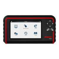
Figure 9-26 Typical Secondary Ignition Signal
9.7 Optional Settings
Home Screen: Tools > Settings> Configure Scope / Meter
The following optional Scope/Meter settings can be set to your preference:
• Trigger Auto/Manual Mode (Optional Setting) on page 90
• Grid (on/off) on page 94
• Trace Divisions on page 95
• Display Settings on page 96
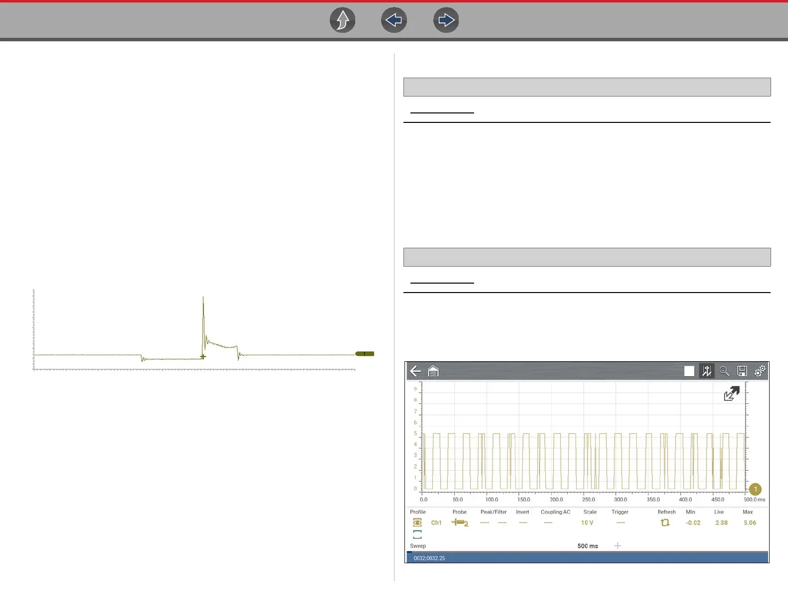
9.7.1 Grid (on/off)
Home Screen: Tools> Settings> Configure Scope / Meter > Grid
The Grid option allows you to display or hide the screen grid lines.
– Show Grid—grid lines on
– Hide Grid—grid lines off
Figure 9-27

 Loading...