Scope Multimeter Operation and Controls
81
9.6.3 Control Panel and Settings
The control panel is common to all three Scope Multimeter functions, and contains
the channel (or “trace”) settings and controls that are used to monitor and adjust the
signal being measured. This section provides a general overview of all the channel
settings and control features used across all three Scope Multimeter functions.
This section is intended as a general overview of the channel settings. Not all
the settings or controls described in this section are applicable with all
functions, some may be “grayed out” or not active (applicable) depending on
the function or test. Function availability is noted as applicable.
The control panel can be toggled on/off by selecting the Expand/Collapse Icon
to switch the screen between full and split test meter views.
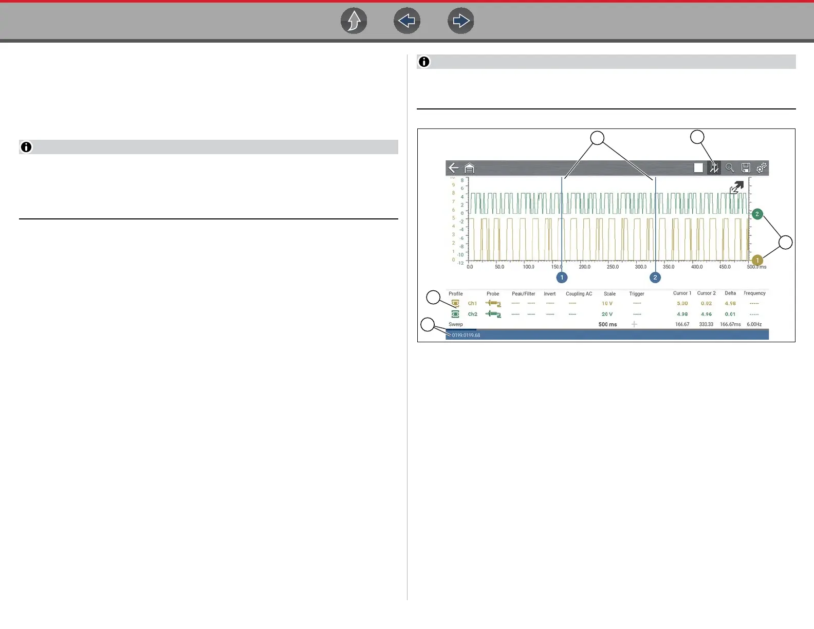
1— Cursors
2— Cursors Icon
3— Zero Base Line Indicators
4— Control Panel—contains channel/trace controls and settings
5— Data Buffer Position Indicators—graphical and numerical position
indicators
Figure 9-13

 Loading...