Fast-Track® Intelligent Diagnostics Smart Data
51
6.8.1 About Smart Data PIDs
Features and operation of Smart Data PIDs:
• Any PID with a flag displayed has been preset and prearmed.
– A red flag indicates the PID trigger has been activated and is operating
out of range.
– A blue outlined flag indicates the PID is armed, and operating within it’s limits
(trigger not activated).
• PID trigger points (upper/lower value limits) are automatically set using known-
good upper/lower limit values.
– Note - Upper/lower limit lines are not displayed on the graph, and values are
not displayed in settings.
• Smart Data PID triggers can be (overridden) set manually, see Using Triggers
on page 36 for instructions.
– Note - Manually setting trigger values will override the preconfigured Smart
Data values.
– Note - Manually set triggers will display upper and lower trigger limit lines in
the graph.
When a trigger is activated:
• Data collection continues briefly after the trigger point, then pauses as the
Scanner captures a recording of the data. Data is saved leading up to and just
past the trigger point.
• An audible alarm is sounded
• A message displays indicating a data file was saved.
• Data collection continues.
• The activated PID trigger is disarmed. Note - if a different PID trigger is
activated subsequently, an additional data file will be recorded.
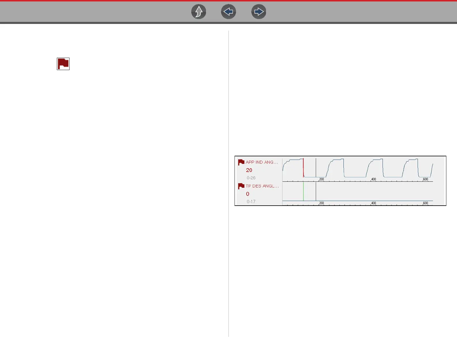
• A red cursor line is displayed on the graph (Figure 6-17) of the PID with the
activated trigger to indicate where the trigger occurred.
• A green cursor line is displayed on all the other PID graphs to indicate their
relationship to where the trigger occurred.
• A gray cursor line is displayed to indicate the point at which the data was
paused to save the data file.
Figure 6-17 Triggers activated

 Loading...