Scope Multimeter Operation and Controls
80
9.6 Operation and Controls
This section describes the general operation and controls used to configure the
scope or meter to perform testing. All three functions share similar control panel
settings, see Control Panel and Settings on page 81 for additional information.
The information in the following sections is intended as a guide and general
overview of the controls and functions used within the Scope Multimeter. Not
all the settings or controls described throughout this section are applicable
with all functions.
z To open a scope multimeter function:
1. Select the Scope Multimeter icon from the home screen.
2. Select either Lab Scope, Graphing Multimeter or Digital Multimeter from
the menu.
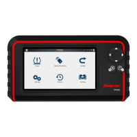
9.6.1 Test Lead / Probe Connection
Standard “safety type” test lead jacks are located on the top of the diagnostic tool,
and are compatible with many test leads and probes (Figure 9-11). Insert the
applicable test lead or probe terminal end into the jack to compete the connection.
To avoid damaging test leads, do not pull on the wire when removing the
leads from their jacks. Pull only on the lead terminal end.
1— Ground Jack (Black)
2— Channel 1 Jack (Yellow)
3— Channel 2 Jack (Green)
Figure 9-11
9.6.2 Test Lead / Probe Calibration
Certain tests may display a confirmation prompt asking “Do you wish to calibrate
this probe?” before continuing with the test. As general practice, it is important to
ensure the test probe is calibrated before testing, to ensure accurate results.
Typical resistance, pressure, and vacuum tests will display the calibration
message, reminding you to calibrate the probe. To perform the probe calibration,
select Yes at the prompt and continue to follow the onscreen instructions to
complete the calibration.
Example: For the ohms (resistance) calibration process, once completed,
zero ohms should be displayed when the leads are connected together. When
the leads are separated, the upward arrows on the display indicate infinite
resistance or an open circuit.
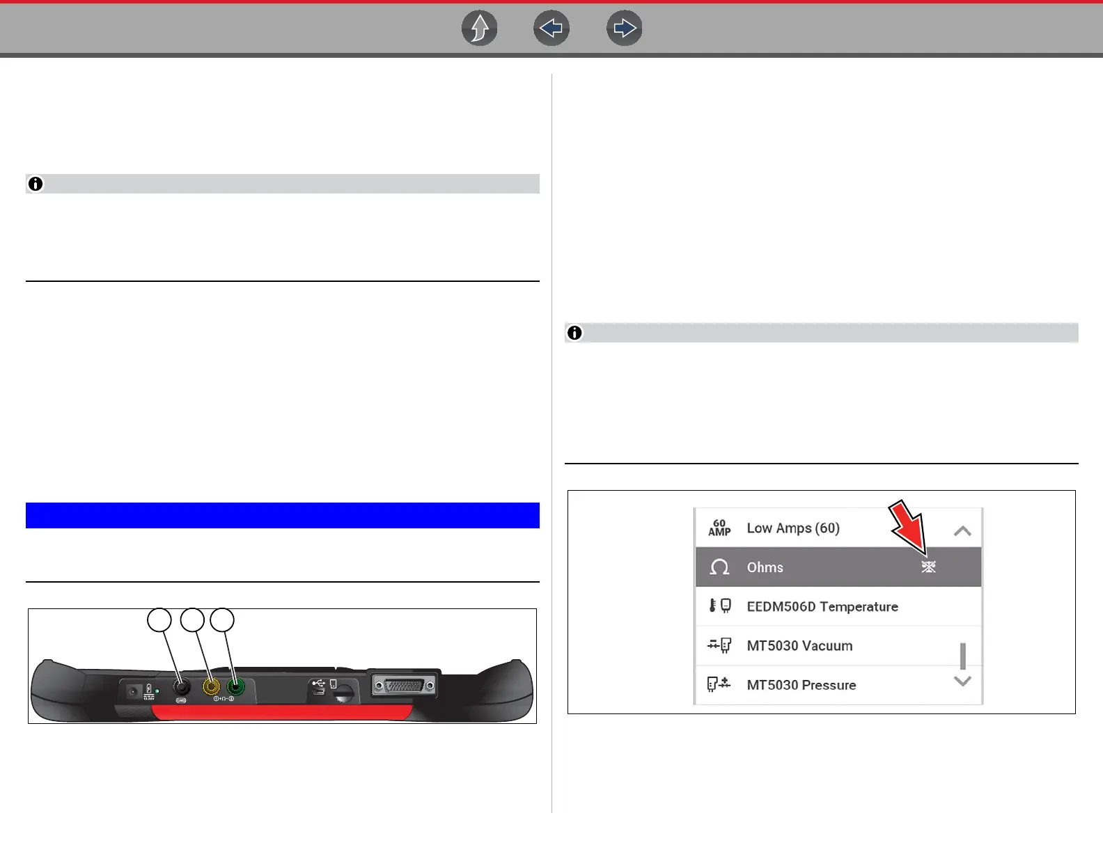
During an ohms test or a pressure test, a manual probe recalibration can be
initiated by selecting the probe icon from the Control Panel to open the probe
menu. Then select either the Ohms or Pressure (100, 500, 5000) items from
the probe menu. The menu selections will display a graphic of a balance scale
with an “X” through it (on right side) to indicate that probe is not calibrated
(Figure 9-12).
Figure 9-12

 Loading...