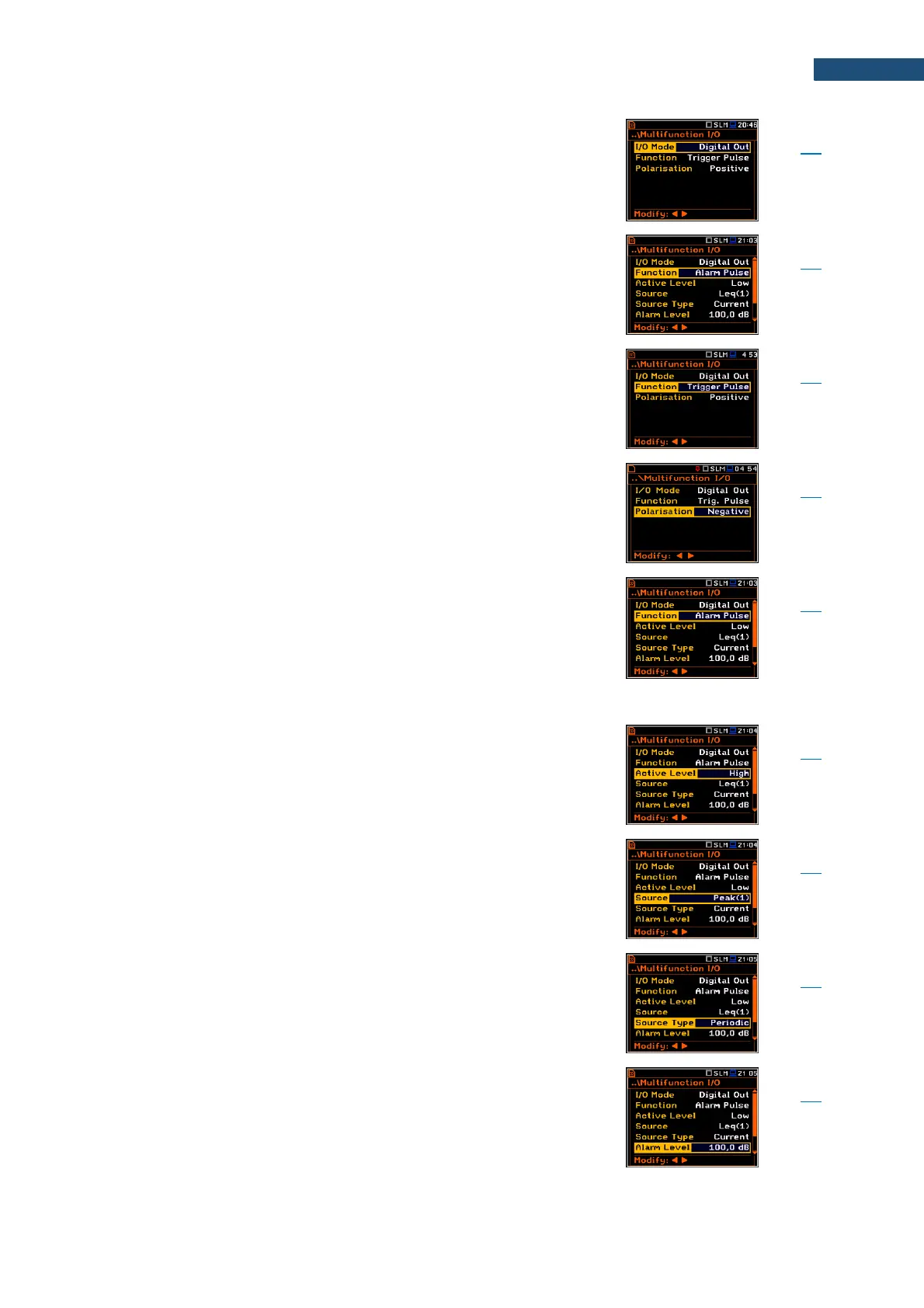
Mode of the I/O port when digital signal is used for
triggering other “slave instrument(s)” (the instrument is
acting in this case as a “master instrument”), or as a
source of alarm signal.
Functionality of the Digital Out I/O mode: Trigger Pulse
or Alarm Pulse.
Functionality of the Digital Out I/O mode when digital
signal used for triggering other “slave instrument(s)” (the
instrument is acting in this case as a “master
instrument”). One additional parameter is used for this
functionality of the Digital Out I/O mode: Polarisation.
Parameter of the Digital Out I/O mode defining which
polarisation of the signal (Negative or Positive) will be
applied to the output trigger pulse.
Functionality of the Digital Out I/O mode when digital
signal is used as a source of alarm signal in case of
certain circumstances occurred during measurements
(i.e. the level of the input signal was higher than a user
selected trigger alarm setting). A set of additional
parameters are used for this functionality of the
Digital Out I/O mode: Active Level, Source,
Source Type, Alarm Level, Send SMS and Send E-mail.
Parameter, when Alarm Pulse is selected as a function
of the Digital Out I/O mode, defining the level of the
signal, treated as an alarm: Low (0 V) or High (3 V).
Parameter, when Alarm Pulse is selected as a function
of the Digital Out I/O mode, defining the measured result,
the level of which should be checked for alarm
generation. The measurement results from the first
profile: Peak(1), Spl(1), Max(1) or Leq(1) can be used.
Parameter, when Alarm Pulse is selected as a function
of the Digital Out I/O mode, defining the type of Source:
Current (measured with 1 second step) or Periodic
(measured with Integration Period step).
Parameter, when Alarm Pulse is selected as a function
of the Digital Out I/O mode, defining the threshold level
of the result to be monitored during the measurement. If
the result is greater than the alarm level, the instrument
will generate the alarm signal in the selected logic.