IV-23
HYDRAULIC UNITS
HST PUMP
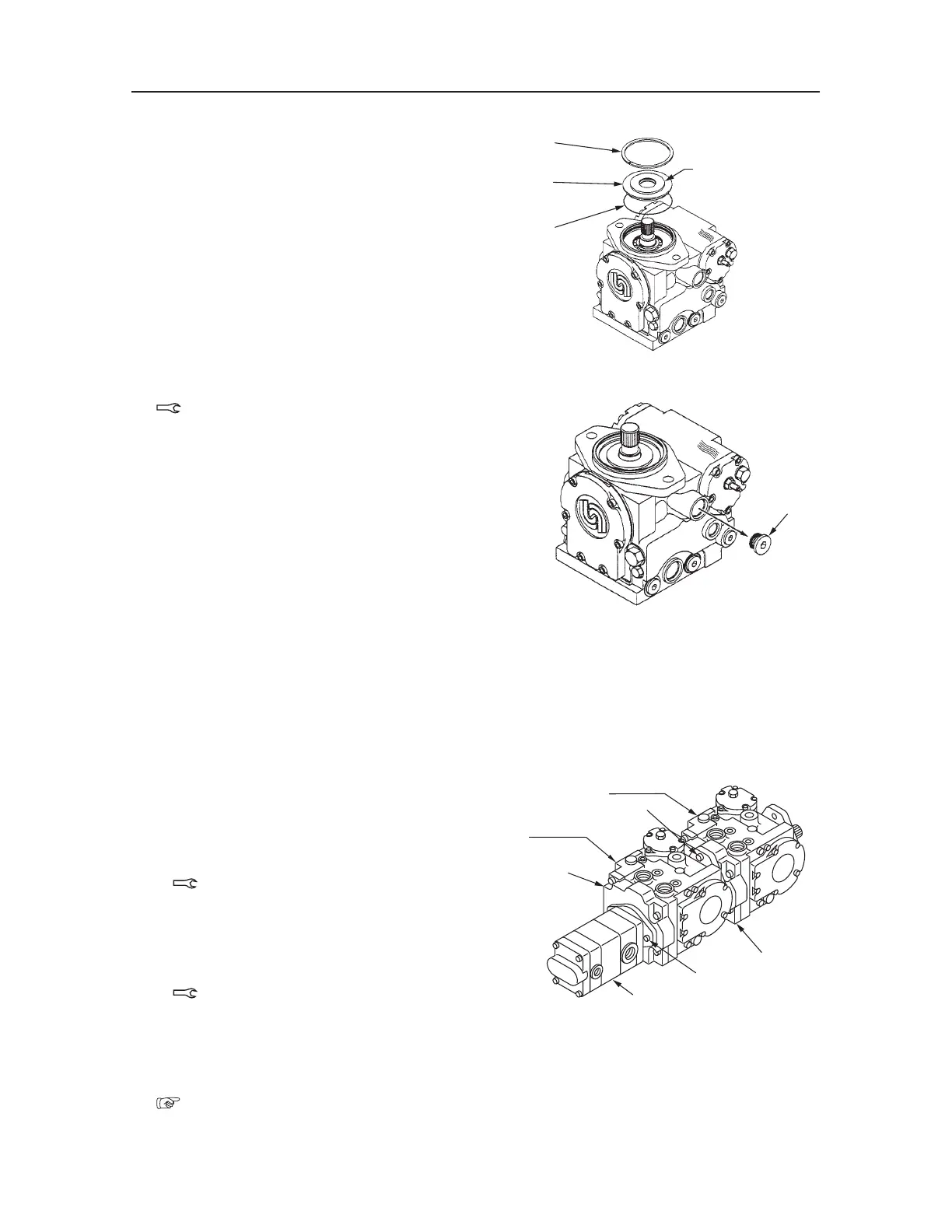
20. Install the seal carrier (7) to the housing, and at-
tach the retaining ring (6).
• Take care not to pinch or damage the O-ring.
• Make sure the retaining ring is installed in the
installation slot of the housing.
21. Install and tighten the drain plug (5).
Drain Plug: 122~257 N·m
22. Perform the idle run torque test.
In order to inspect if the assembling is perfect,
turn the shaft while securing the pump with a
vise.
If the turning is not smooth, reassemble it
again.
• Idle run torque: 12.4 N·m or less
23. Assemble the pumps P1 and P2, and the gear
pump.
a. Attach the O-ring to the B pad adapter (1) of
the pump P1.
b. Combine the pumps P1 and P2, and install the
two bolts (4) and the washer.
Bolt: 91~111 N·m
c. Attach the O-ring to the A pad adapter (3) of
the pump P2.
d. Install the gear pump (2) to the A pad adapter
(3), and tighten them with the two cap screws
(25).
Bolt: 91~111 N·m; Apply Three Bond
#1324
24. Perform neutral adjustment of the pump.
“IV-25~26”
S3F307
6
7
8
A
S3F305E
Pump P1
Pump P2
1
2
4
3
25

 Loading...


