IV-24
HYDRAULIC UNITSHST PUMP
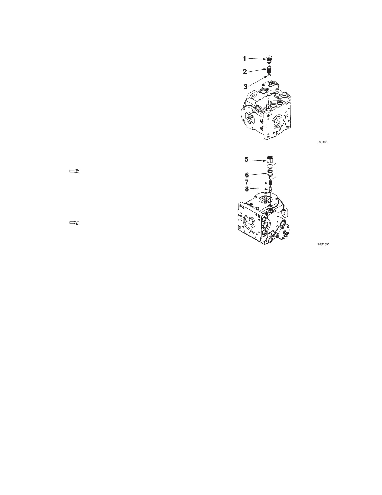
Valves
1. Replace the charge check and high pressure re
-
lief valve.
a. Install outer O-ring, backup ring, and inner
O-ring on each valve seat plug.
b. Check that the conical springs (3) are prop
-
erly retained on the check poppets or relief
valves. Install the check poppet or high pres-
sure relief valve assemblies (2) into the pump
housing.
• The conical springs MUST be correctly
positioned on the check poppets or relief
valves after installation for proper pump
operation.
c. Install the valve seat plugs or valve seat /
bypass plugs (1) into the pump housing and
torque.
Plug: 40~95 N·m
2. Replace the charge relief valve.
a. Install the O-ring on the valve plug. Reinstall
the poppet (8) and spring (7). Reinstall the
plug (6) with its lock nut (5), aligning the
marks made at disassembly.
Lock Nut: 47~57 N·m

 Loading...


