IV-35
HYDRAULIC UNITSGEAR PUMP
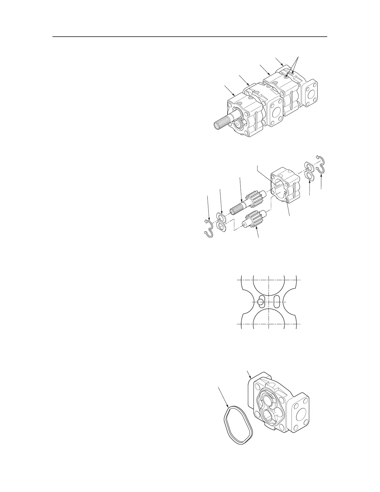
5. Separate the mechanism into its individual com-
ponents: housing (5), adapter plate (6), housing
(7), and rear cover (8).
6. Remove bushing A (9), bushing B (10), drive
gear (11), and driven gear (12) from the front
housing.
• Be careful to keep the bushings separated and
in their original places.
• Be careful not to scratch or otherwise damage
the inside of the housing.
7. Disassemble the rear housing according to the
same procedure as followed for the front hous-
ing.
8. Remove the gasket (13), (14) from bushing A
(9) and bushing B (10).
• Be careful to keep the bushings separated and
in their original places.
9. Remove the gasket (15) from the rear cover (8).
T7D153E
5
6
7
8
MATCH MARK
T7D154E
14
10
11
12
9
13
DISCHARGE SIDE
SUCTION SIDE
T7D155E
DISCHARGE SIDE
SUCTION SIDE
T7D156
8
15

 Loading...


