IV-127
HYDRAULIC UNITS
TRAVEL MOTOR
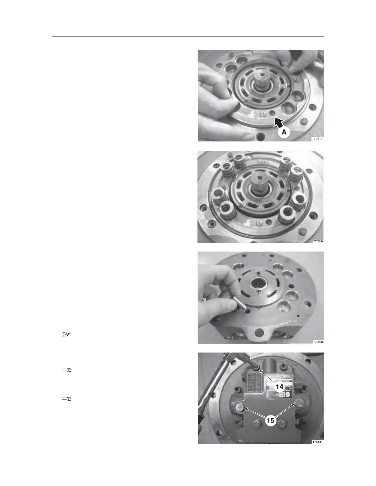
8. Install the brake piston (31) on the flange hold-
er.
• Apply hydraulic oil on the sliding surface of
the cylinder block.
• Be sure that no foreign matter is present in the
cylinder block port.
• The symbol “A” indicates the hole for the
gauge pin.
9. Install the springs (28) on the brake piston (31).
10. Install the O-rings (8, 9, and 35) and the pins (2)
on the flange holder.
11. Install the pin (12) on the valve body (13).
12. Install the valve plate (11) on the valve body
(13).
• Grease the backside of the valve plate.
• The pins (12) must be fitted in the valve plate
groove.
13. Install the gauge pin (32) on the flange holder.
• Align the gauge pin (32) with the pin hole
“A” on the brake piston.
Refer to the step 8 above.
14. Install the valve body (13) and the cap screws
(14).
Cap screw: 60 N·m
15. Install the cap screws (15) on the parking brake
release port.
Cap screw: 100 N·m

 Loading...


