RUN NOW Excite +: Technical Service guide - rev. 6.2
Page 6.11
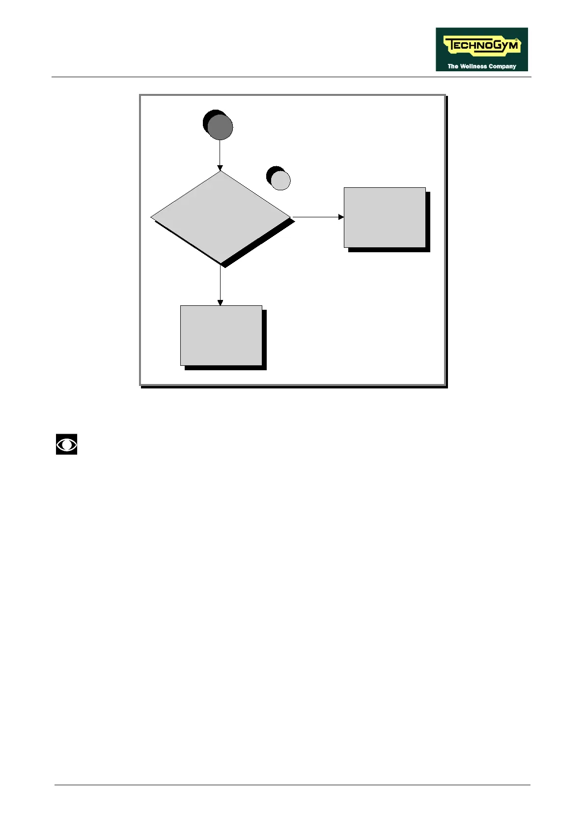
Is the main voltage
to the output of
power supply box?
YES
Replace the cable of
connecting between
Driver
and
Power supply box
NO
Replace the power supply
box
7
A
Follow the procedure step by step to correctly diagnose the problem. Take particular care with the
checks highlighted by circled numbers, which are described in detail below:
To speed up the troubleshooting procedure, check the state of the power indicator LEDs
on the various circuit boards.
(1) Slightly lift the Fast-on connectors on the machine power inlet socket. Place the tester probes
across the live and neutral pins on the same connector. The measured voltage should be
approximately 220Vac/110Vac.
(2) Check if LED 1 and 2 (+5Vdc and +12Vdc), on the ARM board are on.
(3) Check if LED H6 and H3 +5Vdc and +12Vdc (ALE driver), or LED H2 and H3 (AT UL
driver), are on.
(4) Check if on connector J1, there is approximately 220Vac/110Vac, between pin 1 and 2 of the
driver box.
(5) Check the continuity of the power supply signals on the CU242 cables between pin 1 and 5
(AT-UL driver) or on the CU243 cables between pin 1 and 5 (ALE driver), by referring to
paragraph: 2.10. “Cables” and replace what’s defective.
(6) Check if at the output to the Autotransformer there are the 220Vac, on the J1 connector.
(7) Check if the main voltage 220Vac/110Vac is present and the continuity of the on the CU145
cable, pins 1 and 2.