RUN NOW Excite +: Technical Service guide - rev. 6.2
Page 3.27
3.25.2. UNITY + ALE MET / ALEWIN (WITH ADAPTER CABLES)
3.25.2.1. The control
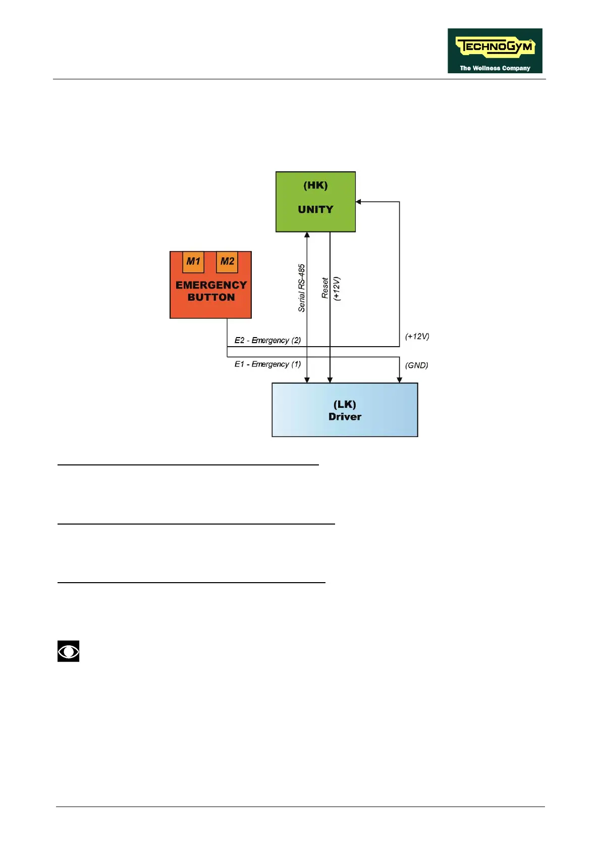
The control block diagram is as follows:
E2 = UNITY (HK) receives the Emergency 2 signal.
• When the system is NOT in emergency the signal is +12V.
• When you press the EMERGENCY signal goes to GND.
E1 = ALE-MET (LK) receives the Emergency 1 signal.
• When the system is NOT in emergency the signal is on GND.
• When you press the EMERGENCY signal goes to +12V.
E1 = ALEWin (LK) receives the Emergency 1 signal.
• When the system is NOT in emergency the signal is GND (pin 9).
• W When you press the EMERGENCY signal goes to +12V.
Driver Note (Low Kit):
• ALE MET and ALEWin: Until the two drivers will coexist, the ALEWin driver will
behave as the ALE-MET. Active Emergency low level (GND).