DCO Setup and Calibration
The ‘G2xxx Value-Line devices take a slightly different approach. Rather than trimming the
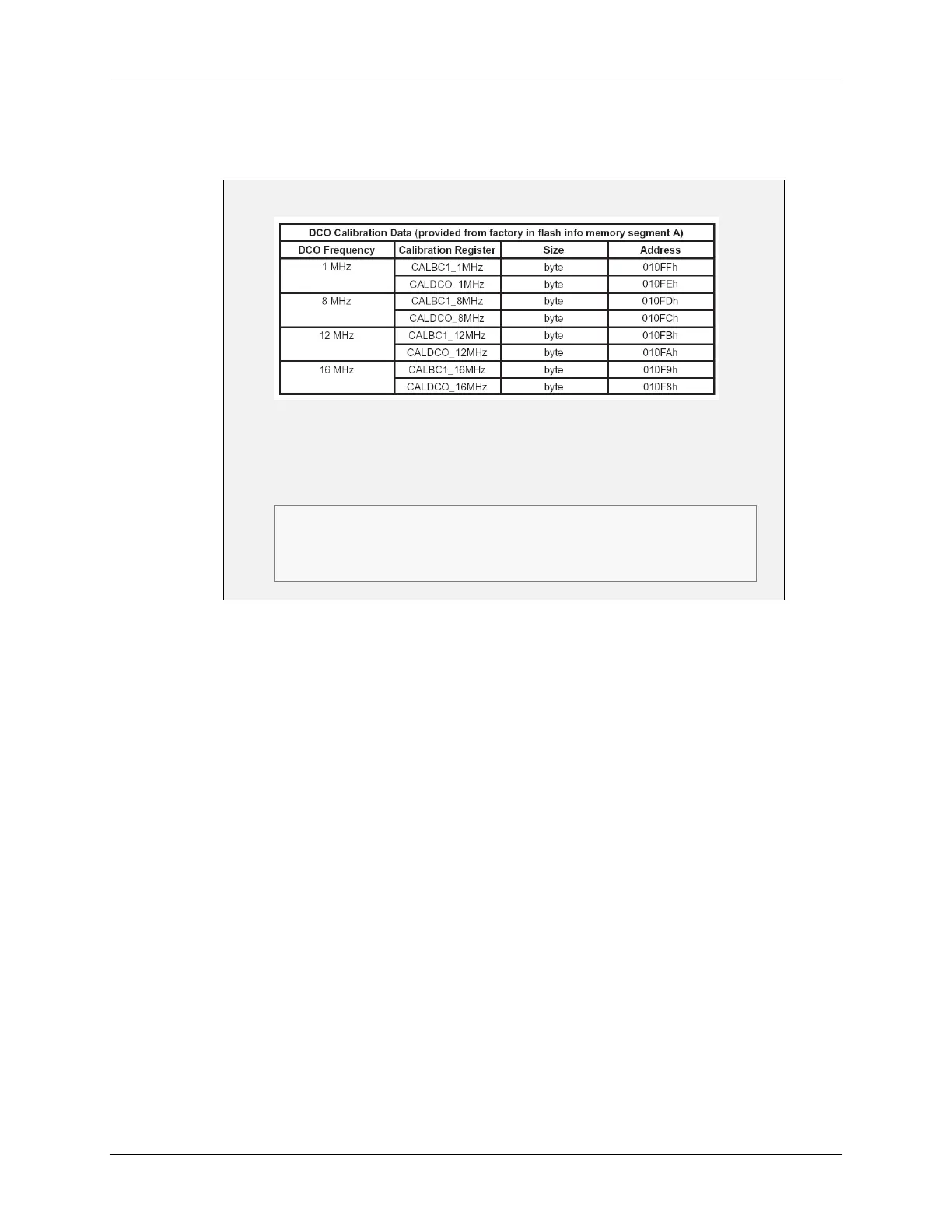
silicon, as is done with the ‘FR5xxx devices, the factory stores calibration values into each
device’s Flash memory (INFOA section) during device test.
‘G2xxx DCO – Calibration Constants
// Setting the DCO to 1MHz
if (CALBC1_1MHZ ==0xFF || CALDCO_1MHZ == 0xFF)
while(1); // Erased calibration data? Trap!
BCSCTL1 = CALBC1_1MHZ; // Set range
DCOCTL = CALDCO_1MHZ; // Set DCO step + modulation
Most G2xx devices provide pre-calibrated clock settings – applying
these sets the Range, DCO, and MCO values
Clock (and ADC) calibration values are calculated at the factory and
stored into Flash memory (INFOA)
G2xx1 provide 1MHz calibration; G2xx2/3 provides all 4 frequencies
Basically, the device tester measures the silicon to determine what value of DCO and MOD is
required to run the DCO at a set of pre-determined frequencies. These calibration values are
stored into INFOA memory by the tester. You can then copy the appropriate calibration constant
from Flash into your DCO control register to run the clock at a specified frequency.
MSP430 Workshop - MSP430 Clocks & Initialization 4 - 27