Operating Modes (Reset → Active)
Operating Modes (Reset → Active)
The MSP430 has a number of operating modes. In this chapter we explore the modes that take
the processor from startup to active. In a future chapter, the low-power modes will be explored.
BOR
The MSP430 starts out in the Brown-Out Reset (BOR) mode. A Brownout Fault (i.e. not enough
power) is the most common event that brings the CPU to this state.
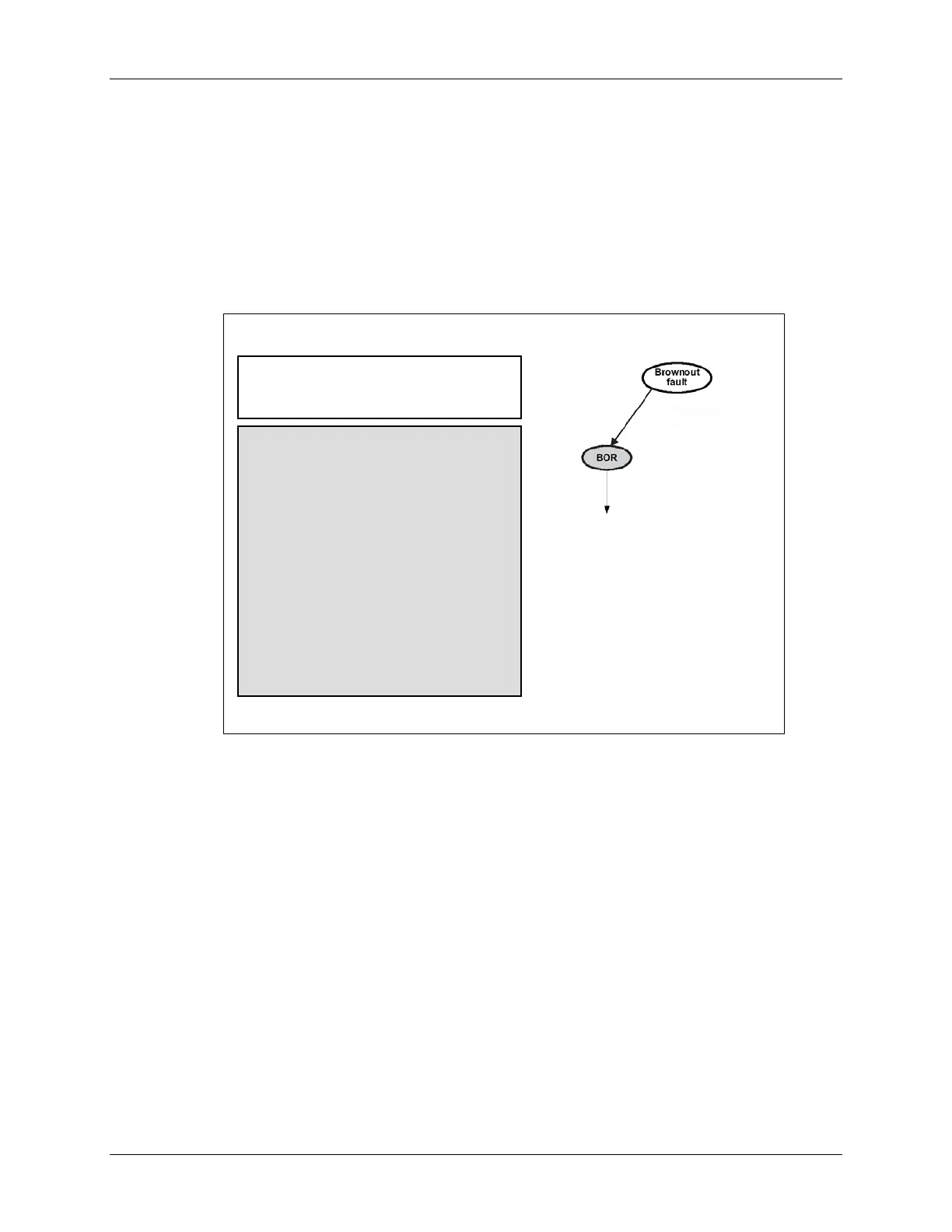
Brownout Reset (BOR)
At power-up, the brownout circuitry
holds device in reset until V
cc
is above
hysteresis point
Startup from BOR:
RST/NMI pin is configured as reset
I/O pins are configured as inputs
Clocks are configured
Peripherals and CPU registers are
initialized (see user guide)
Status register (SR) is reset
Watchdog timer powers up active in
watchdog mode
Program counter (PC) is loaded with
reset vector location (0xFFFE)
If reset vector is blank (0FFFFh), the
device enters LPM4
In BOR, a series of items (listed above) are changed to their default states. (As always, the
device datasheet and users guide should be the final reference as to what is changed in each of
the reset states.)
MSP430 Workshop - MSP430 Clocks & Initialization 4 - 3