MSP430 GPIO
Summary
The following graphic summarizes the GPIO features (and nomenclature) across three MSP430
devices. These three devices provide a good cross-section of MSP430 sub-families:
• The F5529 is an example of the ‘F5xx/6xx series.
• ‘FR5969 is one of the new Wolverine FRAM devices.
• ‘G2553 is the Value-Line processor found on the current Value-Line Launchpad.
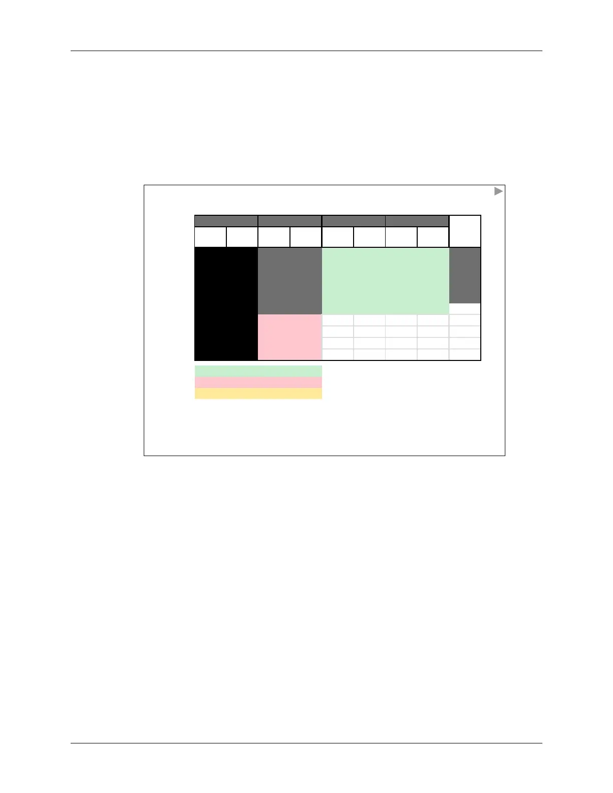
GPIO Summary: F5529 vs FR5969 vs G2553
PA PB PC PD
PJ*
(4-bit )
P1
†
P2 P3 P4 P5 P6 P7
P8
(3-bit)
PxIN
All
Three
Devices
support
Ports 1
and
2
F5529
and
FR5969
(only)
F5529
(only)
F55
&
FR59
PxOUT
PxDIR
PxREN
PxDS
PxSEL
PxIV
FR5969 (only)
PxIES
PxIE
PxIFG
F5529 only (80-pin)
FR5969 only (48-pin)
PJ: 4-bits shared with JTAG pins
G2553 only (20-pin)
P1: 4-bits shared with JTAG pins (‘G2553)
Each numbered port has 8 bits, unless noted otherwise
At reset, all I/O pins are set to … input
You should initialize all pins (to prevent floating inputs)
Analog functions can ‘preempt’ pin function selection
What can we derive from the table above?
• The various GPIO memory-mapped registers are shown here listed down the first column.
Most of these registers were described in the preceding discussion.
• All three devices (and most all MSP430 devices) contain two 8-bit I/O ports (P1, P2) which
provide the GPIO functionality – including interrupt inputs. We demonstrated this above by
using the ‘black’ fill under ports P1 and P2; notice it covers every register’s row.
• Alternatively, you can program ports 1 and 2 simultaneously by writing to port “PA”. This
means by writing to PAOUT, you can concurrently configure the outputs of all 16-pins.
• The ‘G2553 Value-Line device only includes P1 and P2. (There just aren’t enough pins on
this device to support more I/O ports.)
• The new ‘FR5969 Wolverine devices added interrupt support for PB (i.e. ports P3 & P4).
• Only the ‘F5529, of our three example devices, has enough pins to support ports P5 – P8.
Note, though, that the P8 port only contains 3-bits.
• Port PJ is unique. For these devices, it’s only 4-bits wide. These signals represent the 4
JTAG pins; although, any of these four pins can also be reconfigured for GPIO.
3 - 14 MSP430 Workshop - Using GPIO with MSP430ware