EasyManua.ls Logo

Texas Instruments MSP430 Student Guide

Texas Instruments MSP430
398 pages
To Next Page IconTo Next Page
To Previous Page IconTo Previous Page
Page #232 background imageLoading...
Page #232 background image
Lab 5 Interrupts
Lab 5a Push Your Button
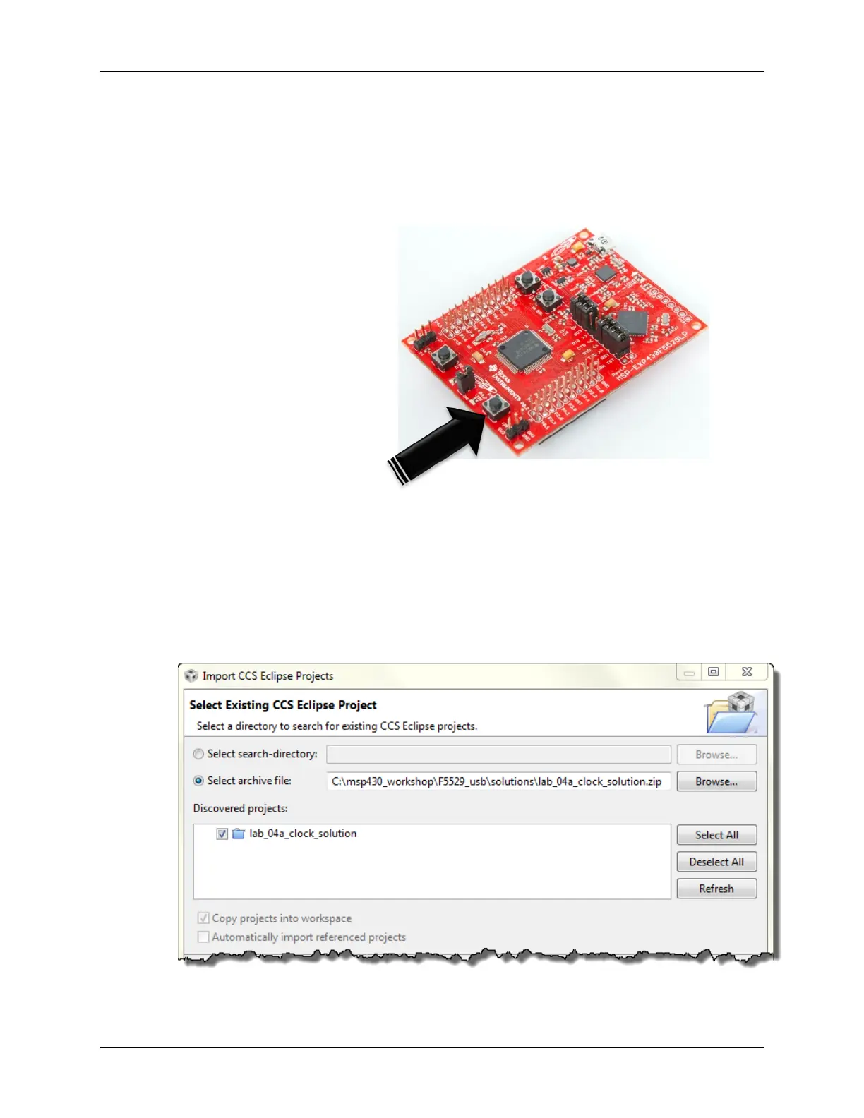
When Lab 5a is complete, you should be able to push the S2 button and toggle the Red LED
on/off.
We will begin by importing the solution to Lab 4a. After which we’ll need to delete a bit of ‘old’
code and add the following.
Setup the interrupt vector
Enable interrupts
Create an ISR
File Management
1. Close all previous projects. Also, close any remaining open files.
2. Import the solution for Lab 4a from: lab_04a_clock_solution
Select import previous CCS project from the Project menu:
Project Import Existing CCS Eclipse Project
5 - 42 MSP430 Workshop - Interrupts

Table of Contents

Other manuals for Texas Instruments MSP430

Question and Answer IconNeed help?

Do you have a question about the Texas Instruments MSP430 and is the answer not in the manual?

Texas Instruments MSP430 Specifications

General IconGeneral
Program Memory TypeFlash
Clock SpeedUp to 25 MHz (depending on the specific device)
Flash MemoryUp to 512 KB (depending on the specific device)
RAMUp to 66 KB (depending on the specific device)
Operating Voltage1.8V - 3.6V (depending on the specific device)
ADC10-bit or 12-bit SAR ADC
Communication InterfacesUART, SPI, I2C, USB
DMAYes (depending on the specific device)
Operating Temperature-40°C to +85°C
Architecture16-bit RISC
Low Power ModesMultiple (LPM0 to LPM4)

Related product manuals