Before We Get Started Coding
3. Pin Unlocking (Wolverine only)
Pin locking is a feature that holds the last state of all GPIO pins when a device is put into its
lowest power modes – that is, when power is removed from the memory and registers. Without
this ‘locking’ feature, the pins would lose their values when these power modes are entered.
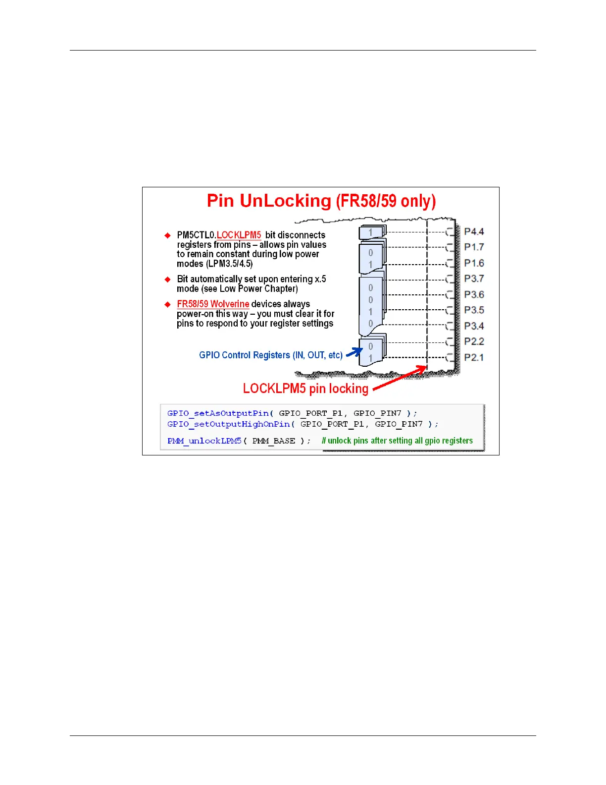
The pin-locking feature freezes the state of each pin. That is, the pins are effectively
disconnected from their associated register bits (i.e. PxOUT) – you can think of there being a
switch along the vertical dashed line shown below.
Many devices prior to Wolverine, such as the ‘F5529, provided the pin-locking feature – although,
it was not enabled by default. The new ‘FR5xxx (Wolverine) devices, though, have this feature
enabled by default … therefore, the pins are always locked at power-up.
When this feature is enabled, there is an additional ‘unlocking’ step required in order for your I/O
to respond to the values written to the GPIO control registers.
As shown above, it is suggested that you setup your GPIO registers and then unlock the registers
using the PMM_unlockLPM5() function.
3 - 18 MSP430 Workshop - Using GPIO with MSP430ware