(Extra Credit) Lab 6b – Timer using Up Mode
(Extra Credit) Lab 6b – Timer using Up Mode
In this timer lab we switch our code from counting in the "Continuous" mode to the "Up" mode.
This gives us more flexibility on the frequency of generating interrupts and output signals.
From the discussion you might remember that TIMER_A has two interrupts:
• One is dedicated to CCR0 (capture and compare register 0).
• The second handles all the other timer interrupts
In our previous lab exercise, we created an ISR for group (non-dedicated) timer ISR. This lab
adds an ISR for the dedicated (CCR0 based) interrupt.
Each of our two ISR's will toggle a different colored LED.
The goal of this part of the lab is to:
// TimerA0 in Up mode using ACLK
// Toggle Green LED every ½ second using TA0IFG
// Toggle Red LED every ½ second using CCR0IFG
Lab 6b Worksheet
1. Calculate the timer period that will go into CCR0 to set the proper interrupt rate.
Here’s a quick review from our discussion.
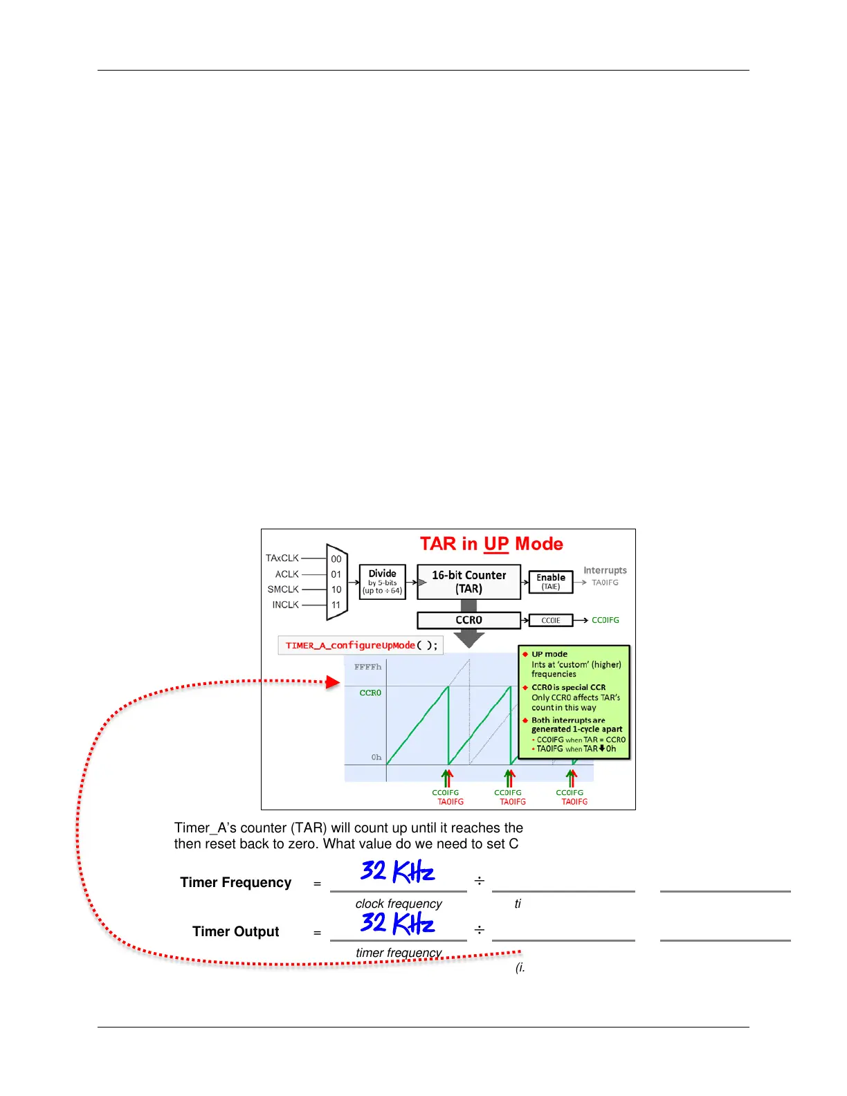
Timer_A’s counter (TAR) will count up until it reaches the value in the CCR0 capture register,
then reset back to zero. What value do we need to set CCR0 to get a ½ second interval?
timer frequency timer period
6 - 44 MSP430 Workshop - Timers