Other Initialization (WDT, PMM)
Operating Voltages
For many of the MSP430 devices, their capabilities can vary based upon the input voltage supply.
For example, most of the devices do not support in-system Flash programming when running
below 2.2V. Another example is that many devices require higher voltages to run at their faster
speeds.
Two examples of this are shown below:
• The ‘F2xx and ‘G2xx devices require 2.2V in order to perform in-system flash programming.
Also, their frequency is proportional to the input voltaage
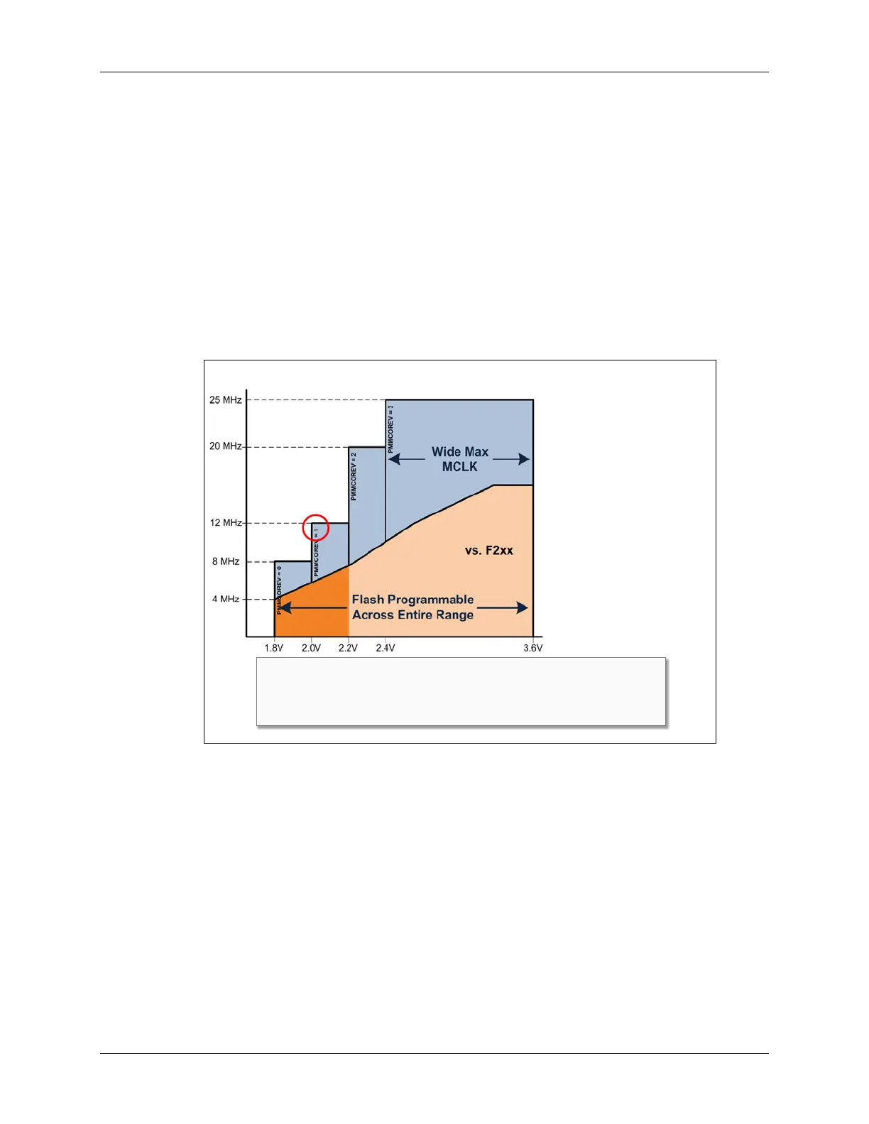
• The F5529 can operate at any one of four voltage ranges. You would need to choose the
input voltage range appropriate for the speed you want to run. For example, if you want to run
at 10MHz you could run at power mode 1, but 25MHz requires power mode 3. On the other
hand, the ‘F5529 can program its flash memory across the entire input voltage range.
‘F5xx Operating Range
25MHz peak performance
More performance
across V
CC
range vs ‘F/G2xx:
Flash ISP @ min. V
CC
8MHz @ min. V
CC
Up to 25MHz @ 2.4V-3.6V
Programmable V
CORE
maximizes power efficiency;
power vs performance
V
CORE
register bits:
PMMCTL0.PMMCOREV
When using SVS, changing
V
CORE
is a 4 step process, but
it’s easy with DriverLib:
PMM_setVCore();
#include <driverlib.h>
//Set VCore = 1 for 12MHz clock
PMM_setVCore( PMM_BASE, PMM_CORE_LEVEL_1 );
The advantage to running with lower power voltage settings is that you, well, save power. The
tradeoff is that you give up capability when you run at the lower settings. Then again, you could
always change the Vcore setting on-the-fly, as needed by your application at any given time.
One big advantage of the new Wolverine devices (e.g. ‘FR5969) is that they can program their
FRAM and run at full speed, even when running at their lowest input voltage. This really helps
them to minimize power while providing you with maximum convenience.
4 - 36 MSP430 Workshop - MSP430 Clocks & Initialization