DCO Setup and Calibration
Factory Callibration (G2xx, FR5xx)
The Value-Line (‘G2xx) and Wolverine (‘FR5xxx) devices use static, pre-calibrated settings,
chosen during device testing, to allow your DCO to meet the frequencies and tolerances specified
in the device datasheet.
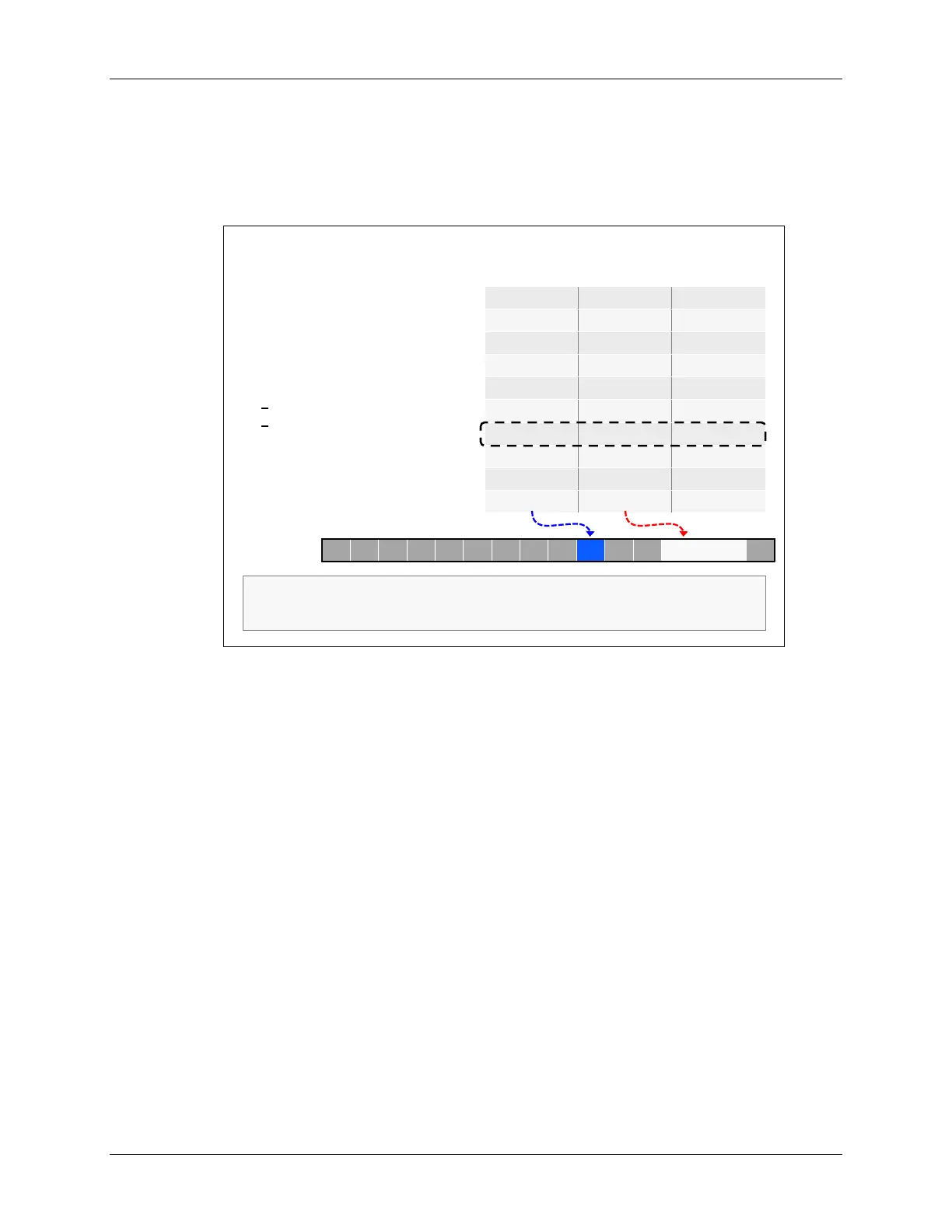
FR5xx DCO – Calibrated Frequencies
Clock System (CS) module
found on FR5xx devices
DCO (CS module) provides
multiple pre-defined &
calibrated frequencies
Factory Trimmed Accuracy:
+2% from 0-50C
+3.5% from -40 to 85C
FR5xx CS module requires psw
to write clock reg’s
*If DCOCLK = 20
or
24MHz it
must be divided down for MCLK
DCORSEL DCOFSEL DCO (MHz)
0 or 1
000 1
0 001 2.667
0 010 3.333
0 011 4
0/1 100/001 5.33
0/1 101/010 6.67
0/1 110/011 8
1 100 16
1 101 20*
1 110 24*
CSCTL1 DCOFSEL
15 14 13 12 11 10 9 8 7 6 5 4 3 2 1 0
// Set DCO to 8MHz
CS_setDCOFreq(CS_BASE, CS_DCORSEL_1, CS_DCOFSEL_3);
Ex:
Configuration of the ‘FR5xxx devices is the easiest of all the MSP430 devices. Looking at the
table in the datasheet (which has been replicated above), you just need to choose the value of
the DCORSEL and DCOFSEL fields to match the frequency you want to run at. The silicon is
trimmed at the factory so that the device meets the accuracy specified in the datasheet.
4 - 26 MSP430 Workshop - MSP430 Clocks & Initialization