Timer Basics: How Timers Work
Timer Basics: How Timers Work
Before we discuss the details of TIMER_A, let’s begin with a quick overview describing how
timers work. Specifically, we will start by describing how a timer is constructed using a Counter
.
Next, we’ll investigate the Capture and Compare capabilities found in many timers.
Counter
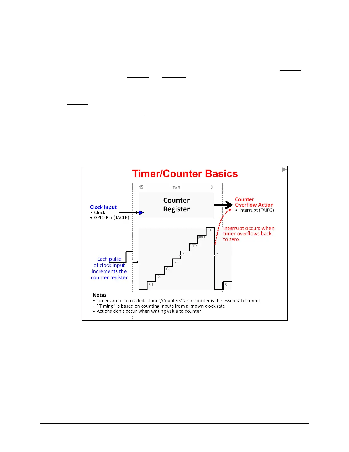
A counter is the fundamental hardware element found inside a timer.
The other essential element is a clock input. The counter is incremented each time a clock pulse
is applied to its clock input. Therefore, a 16-bit timer will count from zero (0x0000) up to 64K
(0xFFFF).
When the counter reaches it reaches its maximum value, it overflows – that is, it returns to zero
and starts counting upward again. Most timer peripherals can generate an interrupt when this
overflow event occurs; on TIMER_A, the interrupt flag bit for this event is called TAIFG (TIMER_A
Interrupt Flag).
The clock input signal for TIMER_A (named TACLK) can be one of the internal MSP430 clocks or
a signal coming from a GPIO pin.
Many engineers call these peripherals “Timer/Counters” as they provide both sets of functionality.
They can generate interrupts or waveforms at a specific time-base – or could be used to count
external events occurring in your system.
One final note about the MSP430 timers: they do not generate interrupts (or other actions) when
you write to the counter register. For example, writing “0” to the counter won’t generate the TAIFG
interrupt.
6 - 6 MSP430 Workshop - Timers