Timer Details: Configuring TIMER_A
2a. Capture: TIMER_A_initCapture()
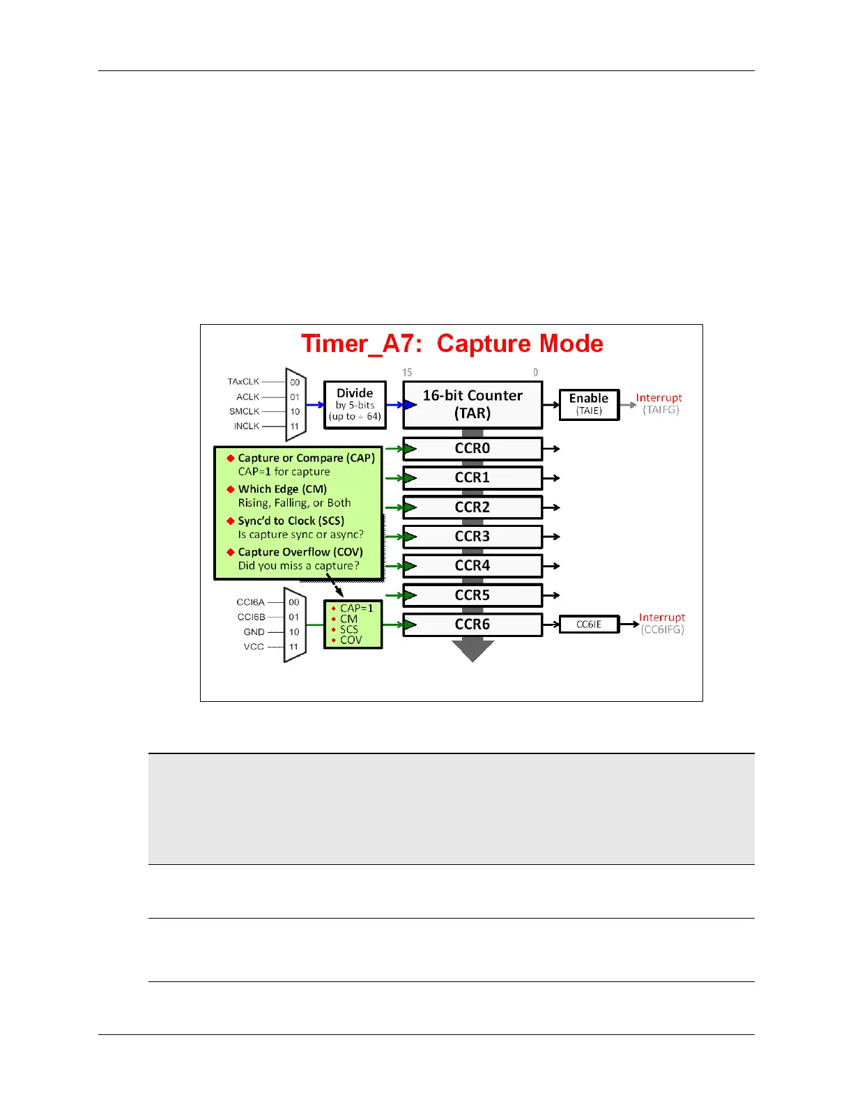
Before we try writing the code to setup a CCR register for Capture, let’s first examine the timer’s
hardware options.
• Most importantly, when wanting to use the Capture features, you need to set CAP = 1.
• The CM bit indicates which clock edge to use for the capture input signal.
• Do you want the capture input signal sync’d with the clock input? If so, that’s what SCS is for.
• While you don’t configure COV, this bit indicates if a capture overflow occurred. In other
words, did a 2
nd
capture occur before you read the captured value from the CCR register?
• Finally, you can select what hardware signal you want to have “trigger” the capture.
Hint: Each CCR can be configured independently. The flip side to this is that you must
configure each one that you want to use; this might involve calling the ‘capture’ and/or
‘compare’ configuration functions multiple times.
Use one for capture and the rest for compare. Or, use all for capture. You get to decide
how they are used.
Warning: If you are using Up or UpDown count modes, you should not configure CCR0. Just
remember that the TIMER_A_configureUpMode() and TIMER_A_configureUpDownMode()
configuration functions handle this for you.
MSP430 Workshop - Timers 6 - 19