Timer Details: Configuring TIMER_A
2b. Compare: TIMER_A_initCompare()
The other use of CCR is for comparisons to the main timer/counter (TAR).
Once again, before we walk through the function that initializes CCR for Compare, let’s examine
its options:
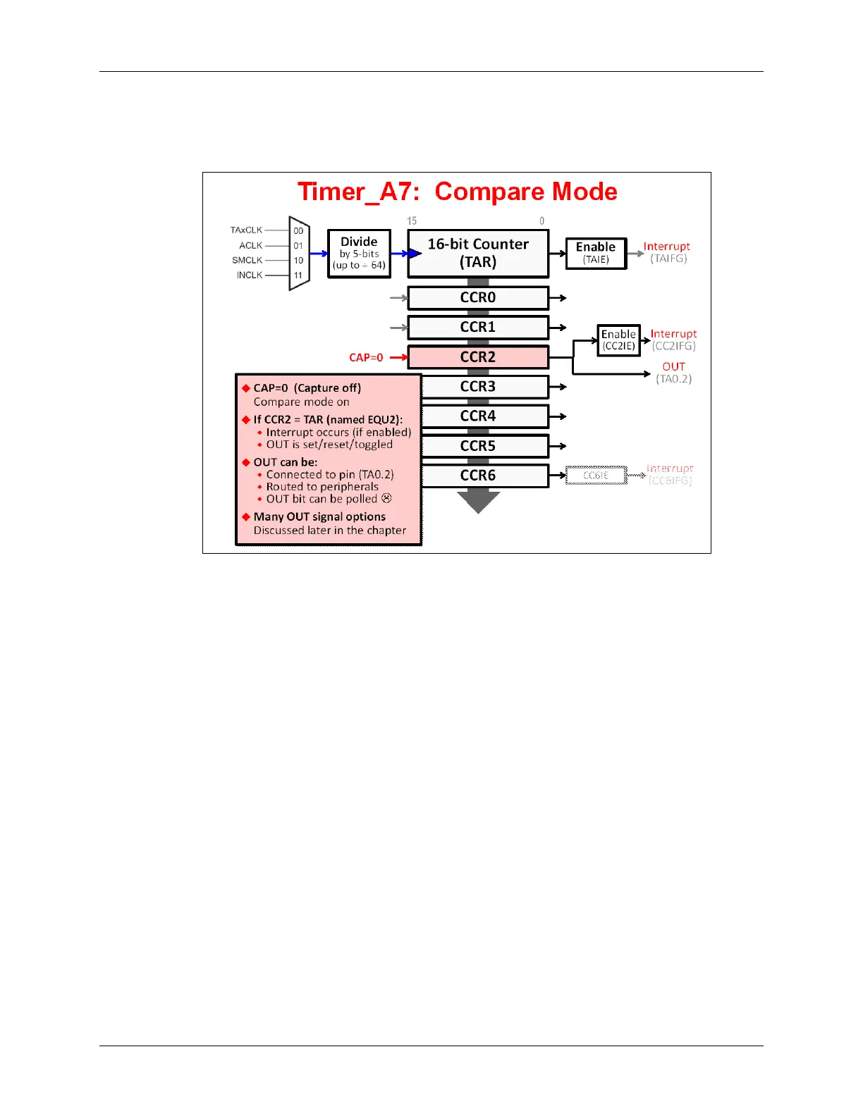
• Set CAP=0 for the CCR to be configured for Compare Mode. (Opposite from earlier.)
• You must set the CCR2 register to a 16-bit value. When TAR = CCR2:
− An internal signal called EQU2 is set.
− If enabled, EQU2 drives the interrupt flag high (CC2IFG).
− Similar to the Capture mode, the CCR’s output signal is modified by EQU2. Again, this
signal is available to other internal peripherals and/or routed to a pin (in this case, TA0.2).
− Again, similar to the Capture mode, there are a variety of possible output modes for the
OUT2 signal (which will be discussed shortly).
MSP430 Workshop - Timers 6 - 21