Timer Details: Configuring TIMER_A
Capture Code Example
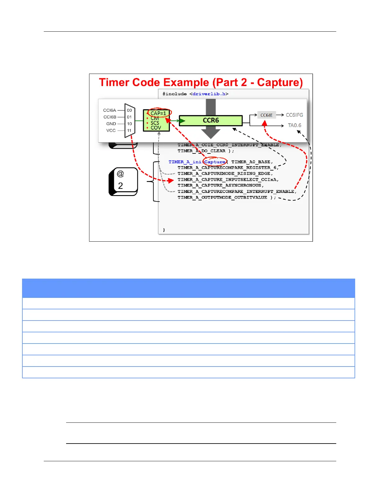
With the Capture mode details in mind, let’s examine the code.
To configure a CCR register for Capture mode, use the TIMER_A_initCapture() function.
Thankfully, when using DriverLib the code is pretty easy to read (and maintain). Hopefully
between the diagram and the following table, you can make sense of the parameters.
Example’s Parameter Value What is Parameter For? Value
TIMER_A0_BASE
Which timer are you using? TA0
TIMER_A_CAPTURECOMPARE_REGISTER_6
Which CCR is being configured? CCR6
TIMER_A_CAPTUREMODE_RISING_EDGE
Which edge of the capture signal are you using? Rising
TIMER_A_CAPTURE_INPUTSELECT_CCIxA
The signal used to trigger the capture CCIn6A
TIMER_A_CAPTURE_ASYNCHRONOUS
Sync the signal to the input clock? No, don’t sync
TIMER_A_CAPTURECOMPARE_INTERRUPT_ENABLE
Enable the CCR interrupt? CC6IE = 1
TIMER_A_OUTPUTMODE_OUTBITVALUE
How should the output signal be handled? OUTMOD=0x0
We’ve briefly talked about every feature (i.e. function parameter) found in this function except
OutputMode. The “OUTBITVALUE” (for CCR6) indicates that the value of CCR6’s IFG bit should
be output to CCR6’s Output signal. The output signal can be used by other peripherals or routed
to the TA0.6 pin.
Note: With regards to OutputMode, this is just the tip-of-the-iceberg. There are actually 8
possible output mode settings. We will take you through them later in the chapter.
6 - 20 MSP430 Workshop - Timers