Timer Details: Configuring TIMER_A
Output Modes
As you may have already seen, each CCR register has its own associated pin. For CCR1 on
Timer0 this pin would be named “TA0.1”. Depending upon which mode you put the CCR into; this
pin can be used as an input (for Compare) or an output (for either Capture or Compare).
When the pin is used as an output, its value is determined by the OUT bit-field in its control
register. The exact details for this are TA0.1 = TA0CCTL1.OUT. (Sometimes you’ll just see this
OUT bit abbreviated as OUT1.)
Besides routing the CCR OUT signal to a pin, it can also be used by other MSP430 peripherals.
For example, on some devices the A/D converter could be triggered by the timer directly.
So, what is the value of OUT for any given CCR register?
The value of OUT is determined by the OutputMode, as we discussed earlier. (Each CCR control
register has its own OUTMOD bit-field). This setting tells the OUT bit how to react as each
compare or capture occurs. As previously stated, there are 8 different OutputMode choices.
For example, setting OUTMOD = 0 tells OUT to follow the value of the CCR IFG bit. Whenever
the IFG bit gets set, so follows OUT. If IFG is set and you clear it, the pin becomes equal to 0.
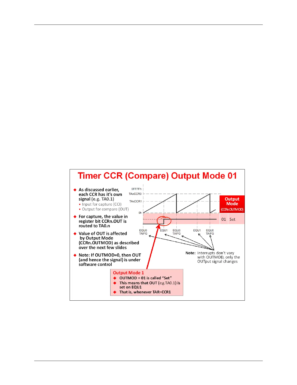
What happens to OUT when OUTMOD = 1 (“Set” mode)?
As we can see from the diagram above, when the timer/counter (TAR) counts up to the value in
CCR1 (i.e. TAR = CCR1), then a valid comparison is true.
The enumeration for OUTMOD = 1 is called “Set”; whenever TAR=CCR1, then OUT will be “Set”
(i.e. OUT = 1). In fact, OUT will remain = 1 until the CCR is reconfigured.
Why use “Set” mode? You might find this mode useful in creating a one-shot type of signal.
6 - 24 MSP430 Workshop - Timers