EasyManuals Logo

Texas Instruments MSP430 Student Guide

Texas Instruments MSP430
398 pages
To Next Page IconTo Next Page
To Previous Page IconTo Previous Page
Page #209 background imageLoading...
Page #209 background image
Interrupts: Priorities & Vectors
Interrupt Vector Table
We can expand the previous interrupt source & priority listing to include a few more items. First of
all, we added a column that provides the IV register associated with each interrupt. (Note, the two
names shown in red text represent the IFG bits for dedicated/individual interrupts.)
Additionally, the first 3 rows (highlighted with red background fill) indicate that these interrupt
groups are non-maskable; therefore, they bypass the GIE bit.
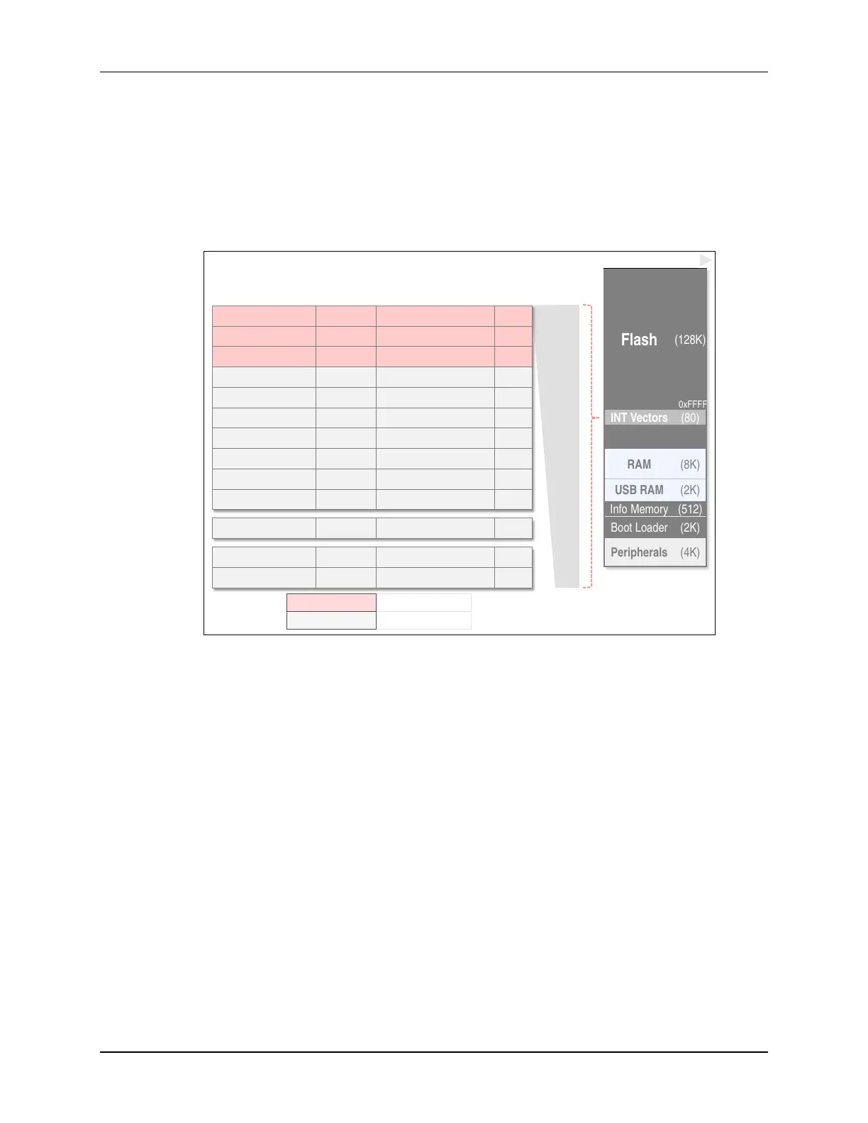
INT Source
IV Register
Vector Address
Loc’n
Priority
System Reset
SYSRSTIV
RESET_VECTOR
63
high
System NMI
SYSSNIV
SYSNMI_VECTOR
62
User NMI
SYSUNIV
UNMI_VECTOR
61
Comparator
CBIV
COMP_B_VECTOR
60
Timer B (CCIFG0)
CCIFG0
TIMER0_B0_VECTOR
59
Timer B
TB0IV
TIMER0_B1_VECTOR
58
WDT Interval Timer
WDTIFG
WDT_VECTOR
57
Serial Port (A)
UCA0IV
USCI_A0_VECTOR
56
Serial Port (B)
UCB0IV
USCI_B0_VECTOR
55
A/D Convertor
ADC12IV
ADC12_VECTOR
54
GPIO (Port 1)
P1IV
PORT1_VECTOR
47
GPIO
(Port 2) P12V
PORT2_VECTOR
42
Real
-Time Clock RTCIV
RTC_VECTOR
41
low
Legend:
Non-maskable
Group’d
IFG bits
Maskable
Dedicated IFG bits
Flash
(128K)
INT Vectors
(80)
RAM
(8K)
USB RAM
(2K)
Info Memory
(512)
Boot Loader
(2K)
Peripherals
(4K)
Memory Map
0xFFFF
Interrupt Vectors & Priorities (F5529)
The final column in the above diagram hints at the location of each interrupts address vector in
the memory map. For example, when using the WDT as an interval timer, you would put the
address of your appropriate ISR into location “57”. As we saw in a previous topic, this can easily
be done using the vector pragma.
The MSP430 devices reserve the range 0xFFFF to 0xFF80 for the interrupt vectors. This means
that for the ‘F5529, the address for the System Reset interrupt service routine will sit at addresses
0xFFFE 0xFFFF. (A 16-bit address requires two 8-bit memory locations.) The remaining
interrupt vectors step down in memory from this point. The map to the right of the table shows
where the interrupt vectors appear within the full MSP430 memory map.
MSP430 Workshop - Interrupts 5 - 19

Table of Contents

Other manuals for Texas Instruments MSP430

Questions and Answers:

Question and Answer IconNeed help?

Do you have a question about the Texas Instruments MSP430 and is the answer not in the manual?

Texas Instruments MSP430 Specifications

General IconGeneral
BrandTexas Instruments
ModelMSP430
CategoryMicrocontrollers
LanguageEnglish

Related product manuals