Timer Basics: How Timers Work
Capture
The Capture feature does just that. When a capture input signal occurs, a snapshot of the
Counter Register is captured; that is, it is copied into a capture register (CCR for Capture and
Compare Register). This is ideal since it solves the problems discussed on the previous page; we
get the timer counter value captured with no latency and very, very little power used (the CPU
isn’t even needed, so it can even remain in low-power mode).
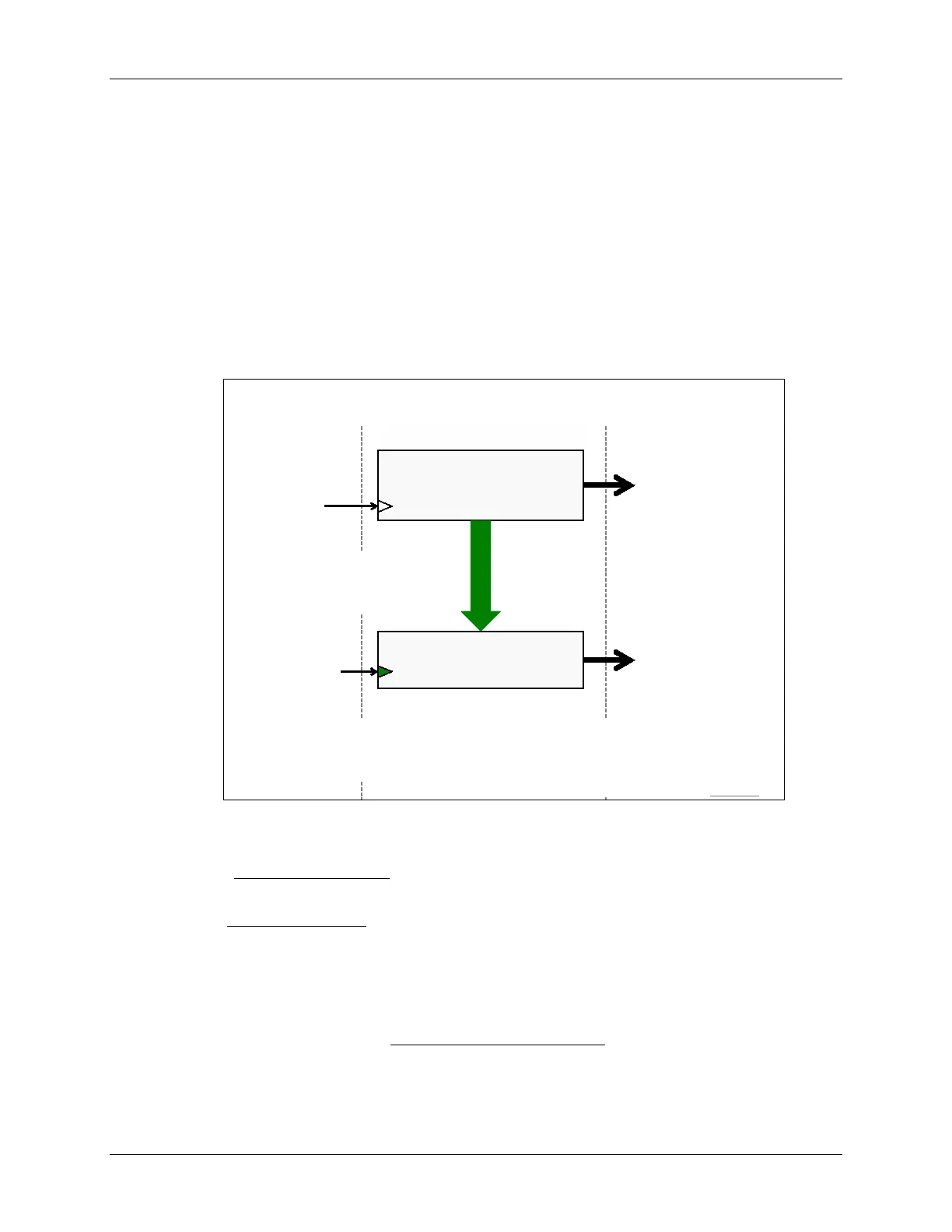
The diagram below builds upon our earlier description of the timer. The top part of the diagram is
the same; you should see the Counter Register flanked by the Clock Input to the left and TAIFG
action to the right.
The bottom portion of the slide is new. In this case, when a Capture Input signal occurs, the value
from the Counter Register is copied to a capture register (i.e. CCR).
Capture/Compare
Register (CCR
n
)
Counter
Register
TAR
Counter
Overflow Action
Interrupt (TAIFG)
Capture Input signal triggers
transfer:
Counter → Capture
Notes
Capture time (i.e. count value) when Capture Input signal occurs
When capture is triggered, count value is placed in CCR and an interrupt is generated
Capture Overflow (COV): indicates 2
nd
capture to CCR before 1
st
was read
Capture Input
CCInA
CCInB
Software
Capture Actions
Interrupt (CCIFGn)
Signal peripheral
Modify pin (TAx.n)
Capture Basics
Alternatively, use CCR for compare...
Clock Input
Clock
GPIO Pin (TACLK)
A few notes about the capture feature:
• As we discussed earlier, the MSP430 timers (TIMER_A, TIMER_B, and TIMER_D)
have multiple CCR registers
; check your datasheet to determine how many are available per
timer peripheral. Each CCR, though, has its own capture input signal.
• The Capture Input signal can be connected to a couple of different signals (CCInA, CCInB) or
triggered in software
• The Capture Input hardware signals (CCInA, CCInB) are connected differently for each CCR
register and device. You need to reference the datasheet to verify what options are available
on your specific device.
• When a capture occurs, the CCR can trigger further actions
. This “action” signal can generate
an interrupt to the CPU, trigger another peripheral, and/or modify the value of a pin.
6 - 8 MSP430 Workshop - Timers