How Interrupts Work
4. Your Software ISR
An interrupt service routine (ISR), also called an interrupt handler, is the code you write that will
be run when a hardware interrupt occurs. Your ISR code must perform whatever task you want to
execute in response to the interrupt, but without adversely affecting the threads (i.e. code)
already running in the system.
Before we examine the details of the ISR; once again, how did we get to this point?
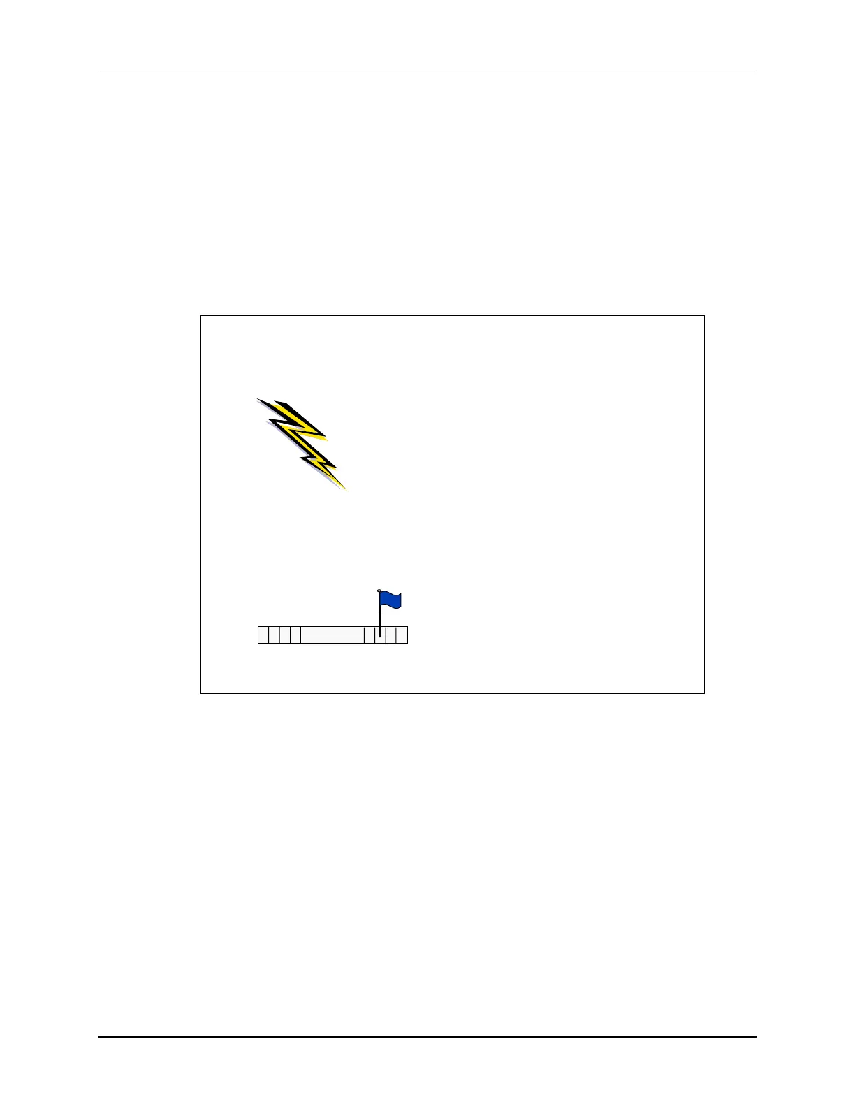
Looking at the diagram below, we can see that (1) the interrupt must have occurred; (2) the processor
flags the incoming interrupt; (3) if enabled, the interrupt flag signal is routed to the CPU where it saves
the Status Register and Return-to address and then branches to the ISR’s address found in the
appropriate location in the vector table. (4) Finally, your ISR is executed.
The crux of the ISR is doing what needs to be done in response to the interrupt; the 4
th
bullet
(listed in red) reads:
• Run your interrupt’s code
This is meant to describe the code you write to handle the interrupt. For example, if it’s a UART
interrupt, your code might read an incoming byte of data and write it to memory.
We’ll discuss the 2
nd
(optional) bullet on the next page.
The 3
rd
bullet indicates that if this is a “grouped” interrupt, you have to add code to figure out
which interrupt, in the group, needs to be handled. This is usually done by reading the group’s IV
register. (This bullet was in red because it is code you need to write.)
The other bullets listed under “4. ISR” are related to saving and restoring the context of the
system. This is required so that the condition mentioned earlier can be met: “without adversely
affecting the code threads already running in the system.”
How do Interrupts Work?
2. Sets a flag bit
(IFG) in register
. . .
• UART
• GPIO
• Timers
• A/D Converter
• Etc.
1. An interrupt
occurs
3. CPU acknowledges INT by…
• Current instruction completes
• Saves return-to location on stack
• Saves Status Reg (SR) to the stack
• Clears most of SR, which turns off
interrupts globally (SR.GIE=0)
• Determines INT source (or group)
• Clears non-grouped flag
*
(IFG=0)
• Reads interrupt vector & calls ISR
4. ISR (Interrupt Service Routine)
• Save context of system
• (optional) Re-enable interrupts
•
*
If group INT, read assoc IV Reg
(determines source & clears IFG)
• Run your interrupt’s code
• Restore context of system
• Continue where it left off (RETI)
5 - 14 MSP430 Workshop - Interrupts