Timer Details: Configuring TIMER_A
PWM anyone?
PWM, or pulse-width modulation, is commonly used to control the amount of energy going into a
system. For example, by making the pulse widths longer, more energy is supplied to the system.
Looking again at the previous example where OUTMOD = 2, we can see that by changing the
difference between the values of CCR0 and CCRn we can set the width of OUTn.
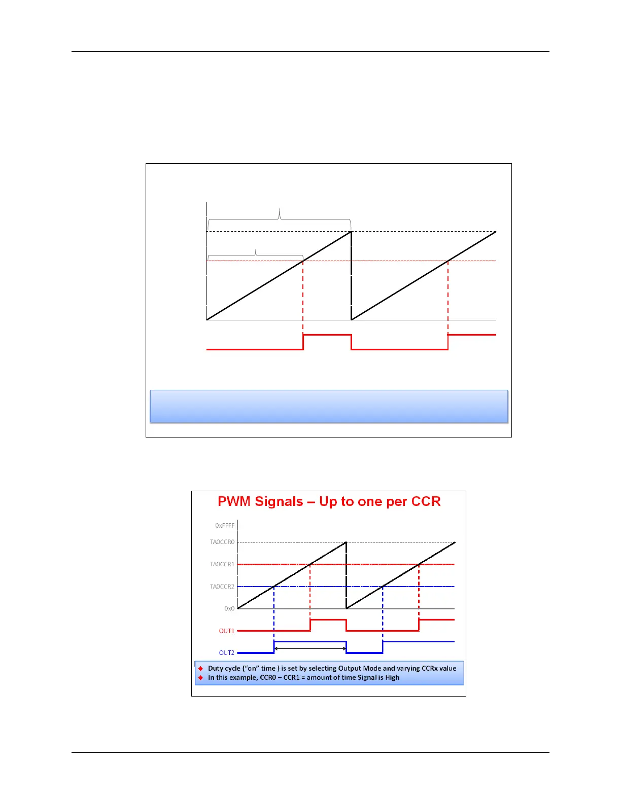
PWM Signals – Up to one per CCR
Duty cycle (“on” time ) is set by selecting Output Mode and varying CCRx value
In this example, CCR0 – CCR1 = amount of time Signal is High
CCR0 sets the time period
CCRn sets duty cycle
In the case of the MSP430, any timer can generate a PWM waveform by configuring the CCR
registers appropriately. In fact, if you are using a Timer_A5, you could output 4 or 5 different
PWM waveforms.
MSP430 Workshop - Timers 6 - 29