MSP430 GPIO
Flexible Pin Useage (Muxing)
Microcontroller designers have to deal with two conflicting user needs:
More Capability vs Lower Cost
Users want as many features as possible on their processors; the more peripheral options, the
better. For example, some users may want 4 serial ports, where others might need 4 I/O ports.
The more pins you add to a device, the greater the cost. (Not only does this make the device
more expensive, but it adds to the overall board/system cost.) Therefore, if we added pins for
every feature stuffed into our microcontrollers, the cost quickly becomes untenable.
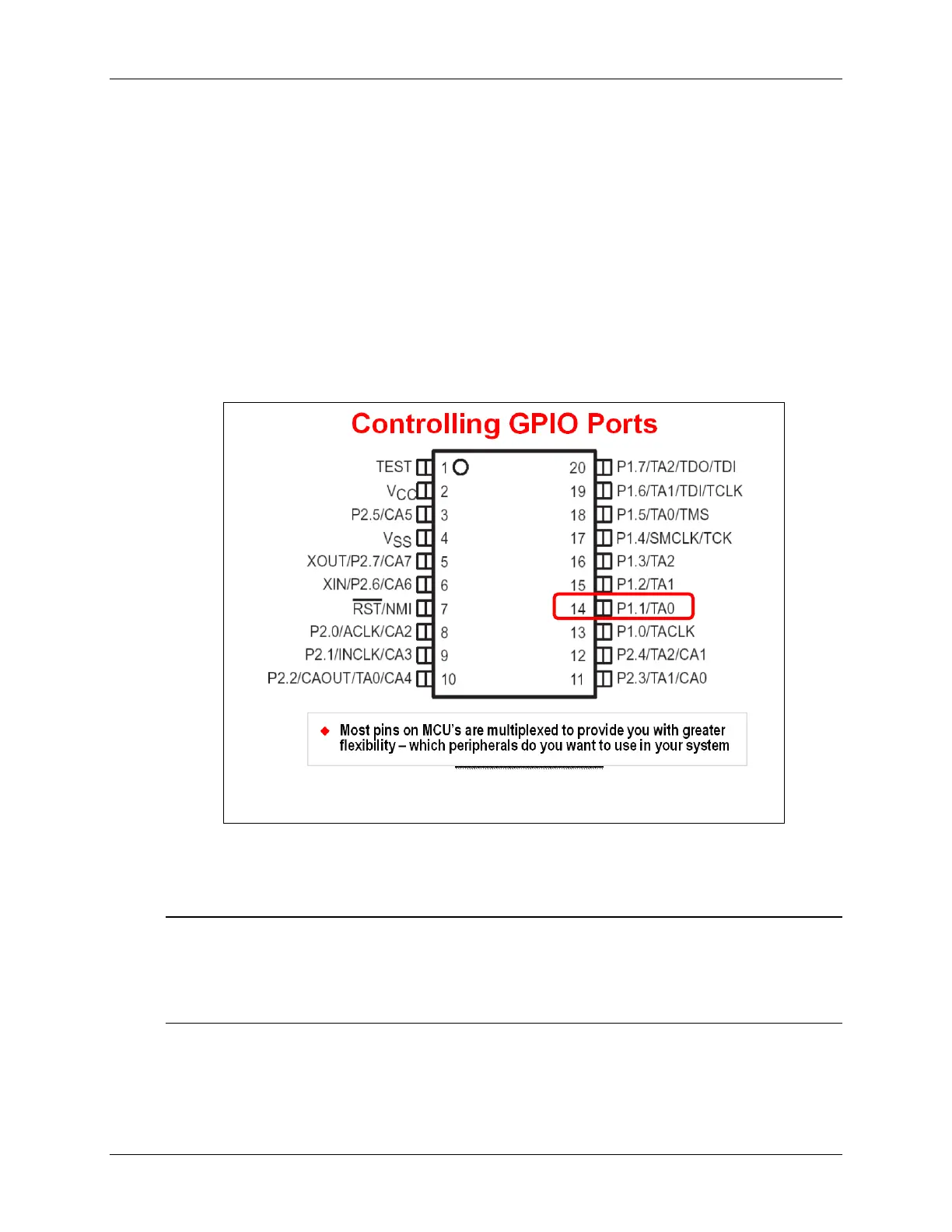
The way this is managed is by ‘muxing’ different functions onto each pin. In other words, you can
select which function you want to use for any given pin on the device. For example, looking at pin
14 in the following diagram, it can be used as either GPIO pin P1.1 or for Timer A0.
While these pin configurations can be changed at runtime, most users do not find this very useful.
The primary reason for this flexibility is so you can choose which features are needed for your
specific system.
Note: Please do not select your specific device – or layout your board’s hardware – before
deciding which features are needed for your system.
If you have done microcontroller system design in the past, this is probably an obvious
statement, but it’s a mistake we’ve seen a number of times in the past.
MSP430 Workshop - Using GPIO with MSP430ware 3 - 11