Timer Details: Configuring TIMER_A
1. Counter: TIMER_A_configure…()
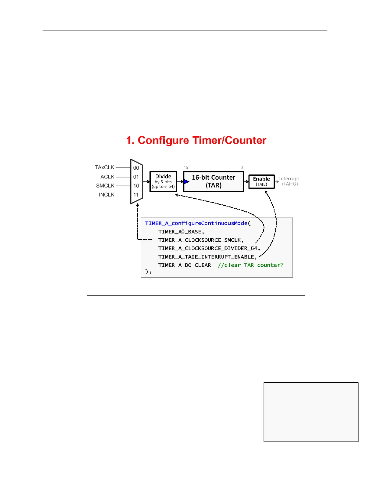
The first step to using TIMER_A is to program the main timer/counter control register. The
MSP430ware Driver Library provides 3 different functions for setting up the main part of the timer:
TIMER_A_configureContinuousMode()
TIMER_A_configureUpMode()
TIMER_A_configureUpDownMode()
We will address the different modes on the next page. For now, let’s choose ‘continuous’ mode
and see how we can configure the timer using the DriverLib function.
From the diagram, we can see that 3 different hardware choices need to be made for our timer
configuration; the arrows demonstrate how the function parameters relate to these choices. Let’s
look at each parameter one-by-one:
• The first parameter chooses which Timer_A instance you want to program. In our example,
we have chosen to program TA0 (i.e. Timer0_A). Conveniently, the DriverLib documentation
provides enumerations for all the supported choices. (This is the same for all DriverLib
parameters, so we won’t keep repeating this statement. But, this is very handy to know!)
• The 2
nd
parameter lets you choose which clock source you want to use. We chose SMCLK.
• The next parameter picks one of the provided clock pre-scale values. The h/w lets you
choose from one of 20 different values; we picked ÷ 64.
• Parameter four lets us choose whether to interrupt the processor
when the counter (TA0R) rolls over to zero. This parameter ends up
setting the TA0IE bit.
• Finally, do you want to have the timer counter register (TA0R) reset
when the other parameters are configured?
Remember…
TAR: Timer_A count Register
TA0R: Name for count register
when referring to instance “0”
(i.e. Timer0_A)
MSP430 Workshop - Timers 6 - 13