MSP430 GPIO
MSP430 GPIO
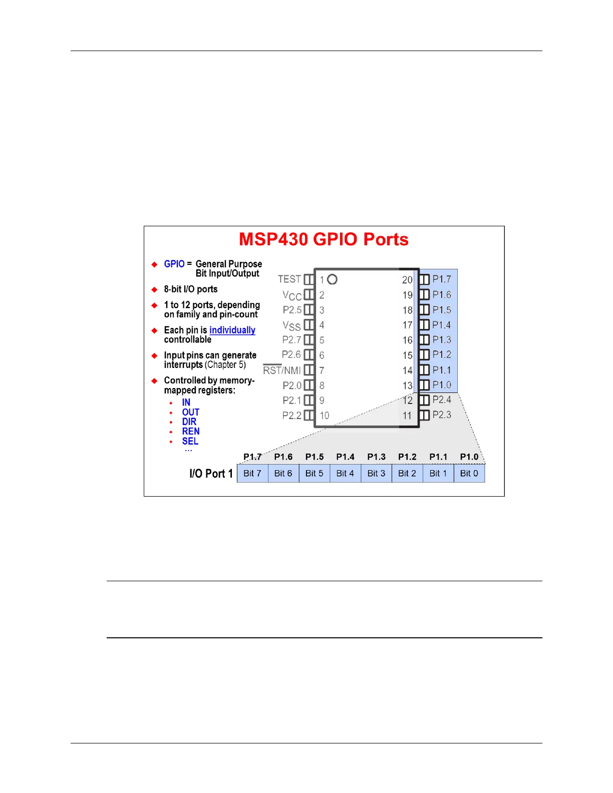
GPIO Basics
General Purpose Bit Input/Output (GPIO) provides a means of controlling – or observing – pin
values on the microcontroller. This is the most basic service provided by processors.
The MSP430 provides one or more 8-bit I/O ports. The number of ports is often correlated to the
number of pins on the device – more pins, more I/O. The I/O port bits (and their related pins) are
enumerated with a Port number, along with the bit/pin number; for example, the first pin of Port 1
is called: P1.0.
Why did we say pin/bit number? Each I/O pin is individually controllable via CPU registers. For
example, if we want to read the input value on P1.0, we can look in bit 0 of the register called
P1IN. There are a number of registers used to view and control the I/O pins. In this chapter we’ll
examine most of them; though, a few – such as those related to interrupts – will be explored in a
later chapter.
Note: As mentioned in the previous paragraph, many GPIO pins can be used to trigger
interrupts to the CPU. The number of pins that support interrupts depends upon which
device you’re using. Most devices support interrupts with Ports 1 and 2, but make sure
you reference your device’s datasheet.
3 - 6 MSP430 Workshop - Using GPIO with MSP430ware